Helical heat exchanger for electric motors

a heat exchanger and electric motor technology, applied in the field of electric motors, can solve the problems of reducing thermal mass, increasing heat production and retention, electric vehicle and system designers are faced not only with cost pressure, but also with downsizing the machinery that they are engineering

Inactive Publication Date: 2016-05-19
ARNOLD MAGNETIC TECH
View PDF0 Cites 25 Cited by
  • Summary
  • Abstract
  • Description
  • Claims
  • Application Information

AI Technical Summary

Problems solved by technology

This is especially evident as devices become smaller, in that these devices now have decreased surface area as well as reduced thermal mass and thermal inertia, which causes higher heat production and retention.
Electric vehicle and system designers are faced not only with cost pressures, but also with downsizing the machinery that they are engineering.
The reasoning for using laminated steel in these areas is to reduce Eddy currents that are formed during the changes in the flow of electrons, which cause an increase in heating of the motor and reduced performance.
By using very thin laminations, only small Eddy currents are formed, which lead to minimal power reductions and heat production.
It is these Eddy currents, and natural copper resistance losses, along with other minimal contributors, that cause a motor to heat.
However, air has much less heat transfer capability than some liquids, such as water or oil.
This is due to the fact that air flow cannot efficiently transfer enough heat out of the electric motor, resulting in electric motor sizes being constrained.
Often liquid flow becomes laminar and does not effectively “scrub” heat off of the hot surface of the floor of the waterjacket, which may impact the compactness of the electric motor design.
However, such cooling systems are typically hard to cast, and in the cast of the installed rod method are typically hard to machine and employ.

Method used


Image

  • Helical heat exchanger for electric motors
  • Helical heat exchanger for electric motors
  • Helical heat exchanger for electric motors

Examples


first embodiment

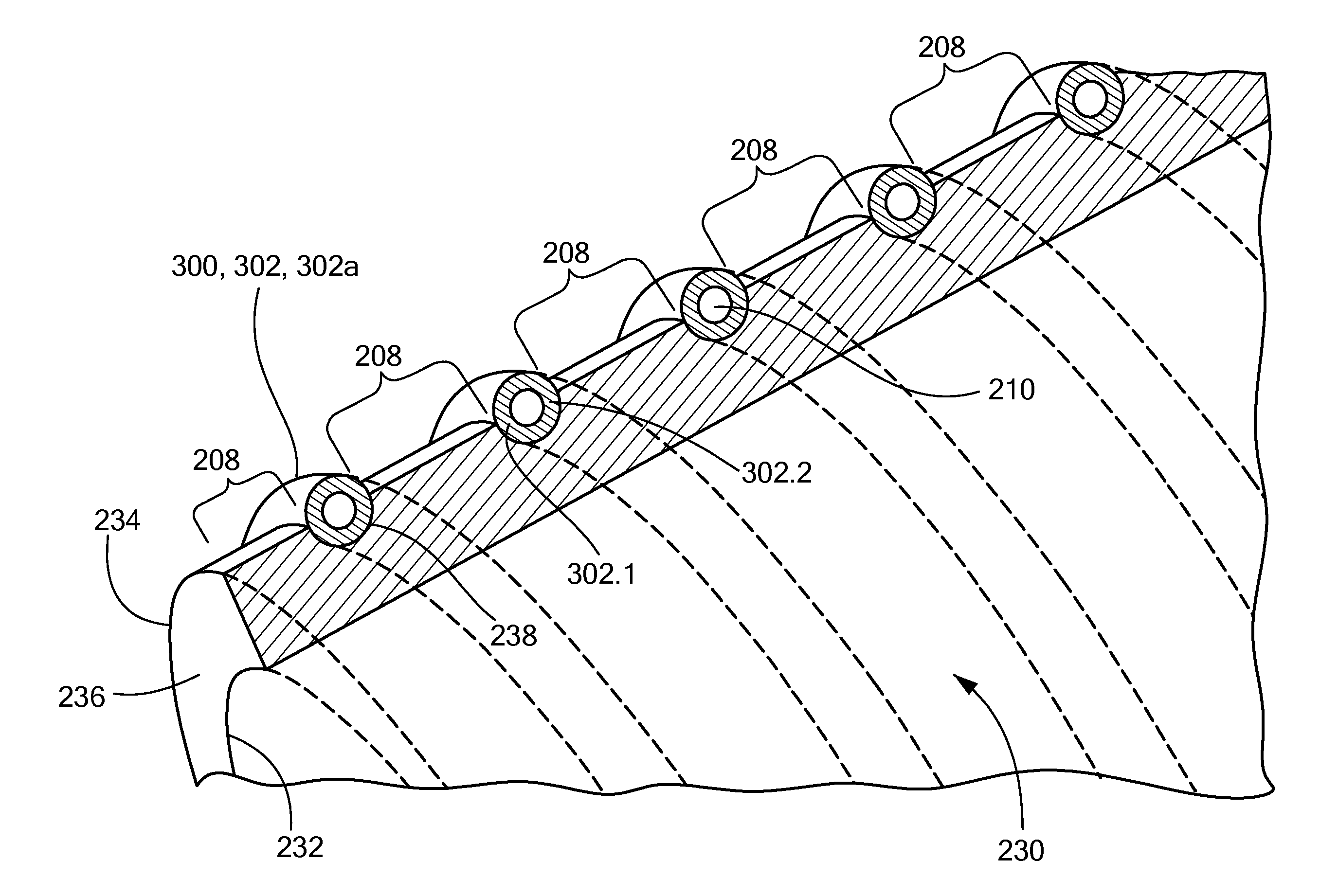
[0032]In a first embodiment where the helix member is a solid helix member 302a (illustrated in FIG. 3 as being hollow, but understood to be solid when herein referred to as “a solid helix member 302a”), the solid helix member 302a itself forms a single helical wall between the inner and outer sleeves 230, 280, which in turn forms a single helical fluid flow path 208 between the inner and outer sleeves 230, 280 that extends from the one end 204 to the opposite end 206 of the inner and outer sleeves 230, 280.

[0033]In a second embodiment where the helix member is a hollow helix member 302 (as illustrated in FIG. 3), the hollow helix member 302 itself, by virtue of the tubular wall construction, forms two helical walls 302.1, 302.2 between the inner and outer sleeves 230, 280, which in turn forms two helical fluid flow paths 208, 210 between the inner and outer sleeves 230, 280 that extends from the one end 204 to the opposite end 206 of the inner and outer sleeves 230, 280, where the ...

fourth embodiment

[0038]In a fourth embodiment, and with reference now to FIG. 6, the at least one helical wall 300, instead of being provided by a helix member, is provided by a helical rib 304 that is integrally formed with and extends outward from the first outer surface 234 of the inner sleeve 230. The helical rib 304 itself forms a single helical wall between the inner and outer sleeves 230, 280, which in turn forms a single helical fluid flow path 208 between the inner and outer sleeves 230, 280 that extends from the one end 204 to the opposite end 206 of the inner and outer sleeves 230, 280.

fifth embodiment

[0039]In a fifth embodiment, and with reference to FIG. 7, the at least one helical wall 300 is provided by first and second helical ribs 304, 306 that are integrally formed with and extend outward from the first outer surface 234 of the inner sleeve 230 to form two helical walls between the inner and outer sleeves 230, 280 that extend from the one end 204 to the opposite end 206 of the inner and outer sleeves 230, 280. The second helical rib 306 is disposed in helical equidistance from the first helical rib 304 to provide a space therebetween of uniform cross-section along the helical paths defined by the first and second helical ribs 304, 306. The space outboard of the first and second helical ribs 304, 306 forms a first helical fluid flow path 208, and the space inboard (between) the first and second helical ribs 304, 306 forms a second helical fluid flow path 210. The similarities between the first and second fluid flow paths 208, 210 of FIG. 7 and the first and second fluid flo...


PUM

PropertyMeasurementUnit
volumeaaaaaaaaaa
thicknessaaaaaaaaaa
torqueaaaaaaaaaa

Abstract

An electric motor has a stator, a rotor, and a helical heat exchanger disposed outboard of the stator. The helical heat exchanger includes: an inner sleeve; an outer sleeve coaxially disposed with and outboard of the inner sleeve with a void therebetween; at least one helical wall disposed in the void between the inner and outer sleeves extending from one end to an opposite end of the inner and outer sleeves; the at least one helical wall forming a fluid tight seal along its helical path to define at least one helical fluid flow path in the void between the inner and outer sleeves; and the at least one helical fluid flow path configured to permit at least one heat transfer medium to helically travel within the void between the inner and outer sleeves.

Description

BACKGROUND OF THE INVENTION[0001]The present disclosure relates generally to electric motors, more particularly to heat exchangers for electric motors, and even more particularly to a helical heat exchanger for electric motors.[0002]As electric motors, and other mechanical devices, are driven to their limits in a, variety of applications, it is becoming more cost competitive to use a smaller device and drive it harder and / or faster. Increasing the torque and speed output of such a device results in the production of more power output, as well as heat.[0003]Heat removal is an important factor to driving these devices harder and faster. This is especially evident as devices become smaller, in that these devices now have decreased surface area as well as reduced thermal mass and thermal inertia, which causes higher heat production and retention.[0004]Electric vehicle and system designers are faced not only with cost pressures, but also with downsizing the machinery that they are engine...

Claims


Application Information

Patent Timeline
Patent Type & Authority Applications(United States)
IPC IPC(8): H02K1/20B23K20/10H02K15/02B23K31/02
CPCH02K1/20H02K15/02B23K20/10B23K31/02H02K5/203
Inventor KUBES, LARRY A.
Owner ARNOLD MAGNETIC TECH
Why Eureka
Try Eureka