
Power supply circuits for gate drivers

a technology of power supply circuit and gate driver, which is applied in the direction of power conversion system, oscillation generator, pulse technique, etc., can solve the problems of decreasing the supply voltage to levels that affect the performance of the gate driver itself, and the initialization of the electrically floating supply voltage typically requires an undesirably prolonged startup sequen

Active Publication Date: 2016-05-19
ANALOG DEVICES INC
View PDF1 Cites 8 Cited by
  • Summary
  • Abstract
  • Description
  • Claims
  • Application Information

AI Technical Summary

Benefits of technology

The patent text describes an improved power supply circuit for driving loads in various applications. The circuit provides isolated and / or electrically floating supply voltages to the load driving circuit, which is necessary for safety and reliability concerns. The circuit also addresses the issue of initializing the electrically floating supply voltage by using a low side gate driver and a separate control circuit. The technical effects of the circuit include improved power supply efficiency, reduced impact on the performance of the gate driver, and improved safety and reliability. The patent also describes various embodiments of the circuit and its applications, such as in polyphase systems and control circuits.

Problems solved by technology

One difficulty in providing an electrically floating supply voltage to a high side gate driver is that the gate driver draws energy from the source of the supply voltage while driving the load, potentially decreasing the supply voltage to levels that impact the performance of the gate driver itself.
Another difficulty is that initializing the electrically floating supply voltage has typically required an undesirably prolonged startup sequence involving the low side gate driver.

Method used


Image

  • Power supply circuits for gate drivers
  • Power supply circuits for gate drivers
  • Power supply circuits for gate drivers

Examples


Embodiment Construction

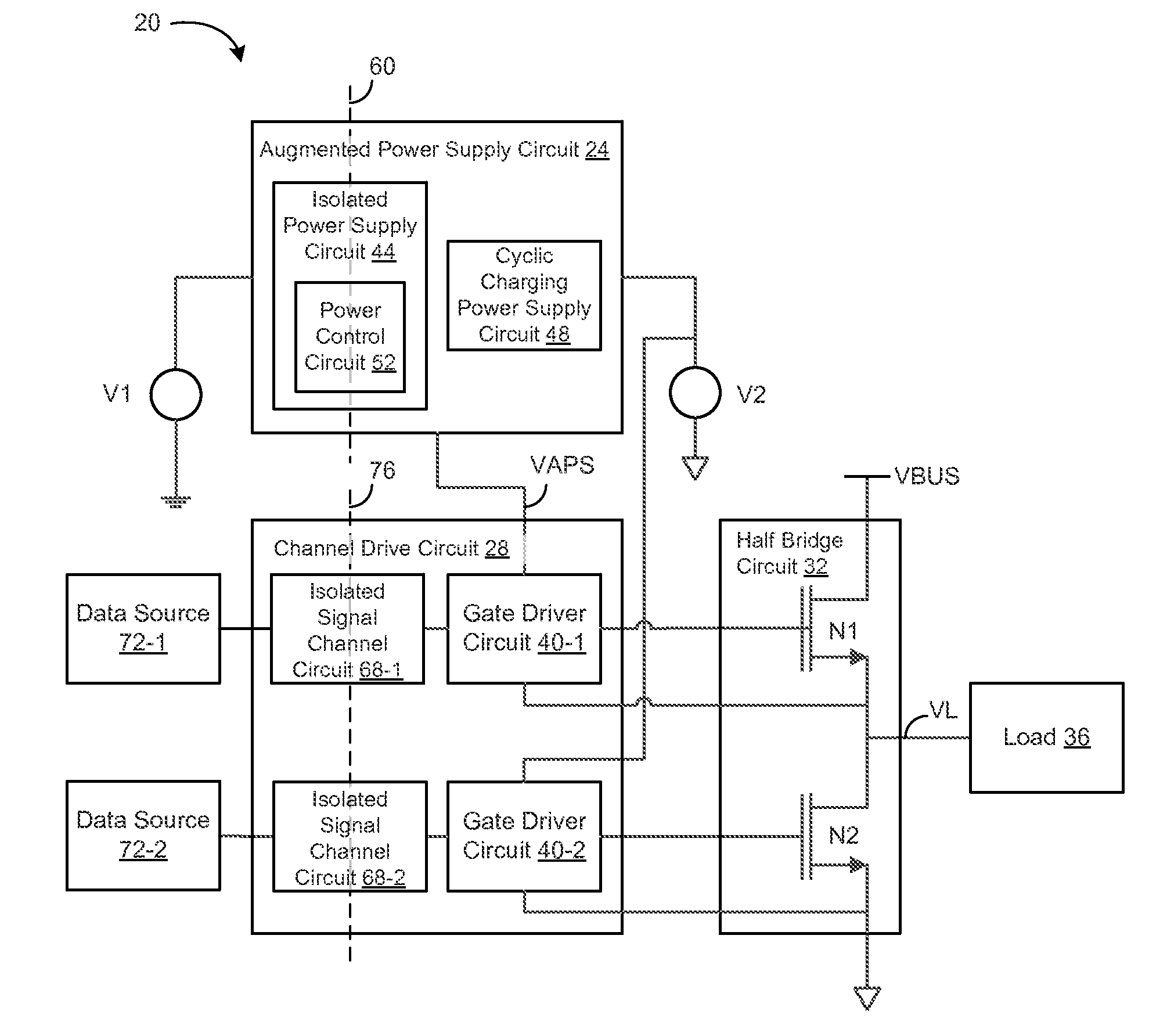
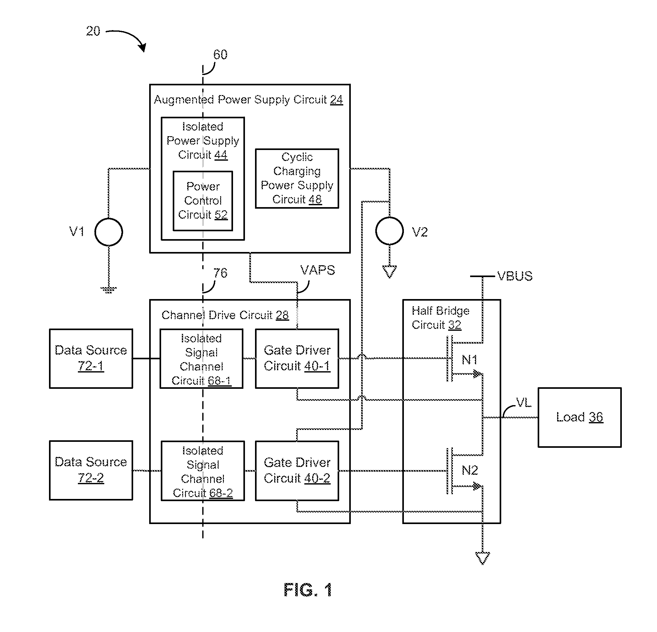
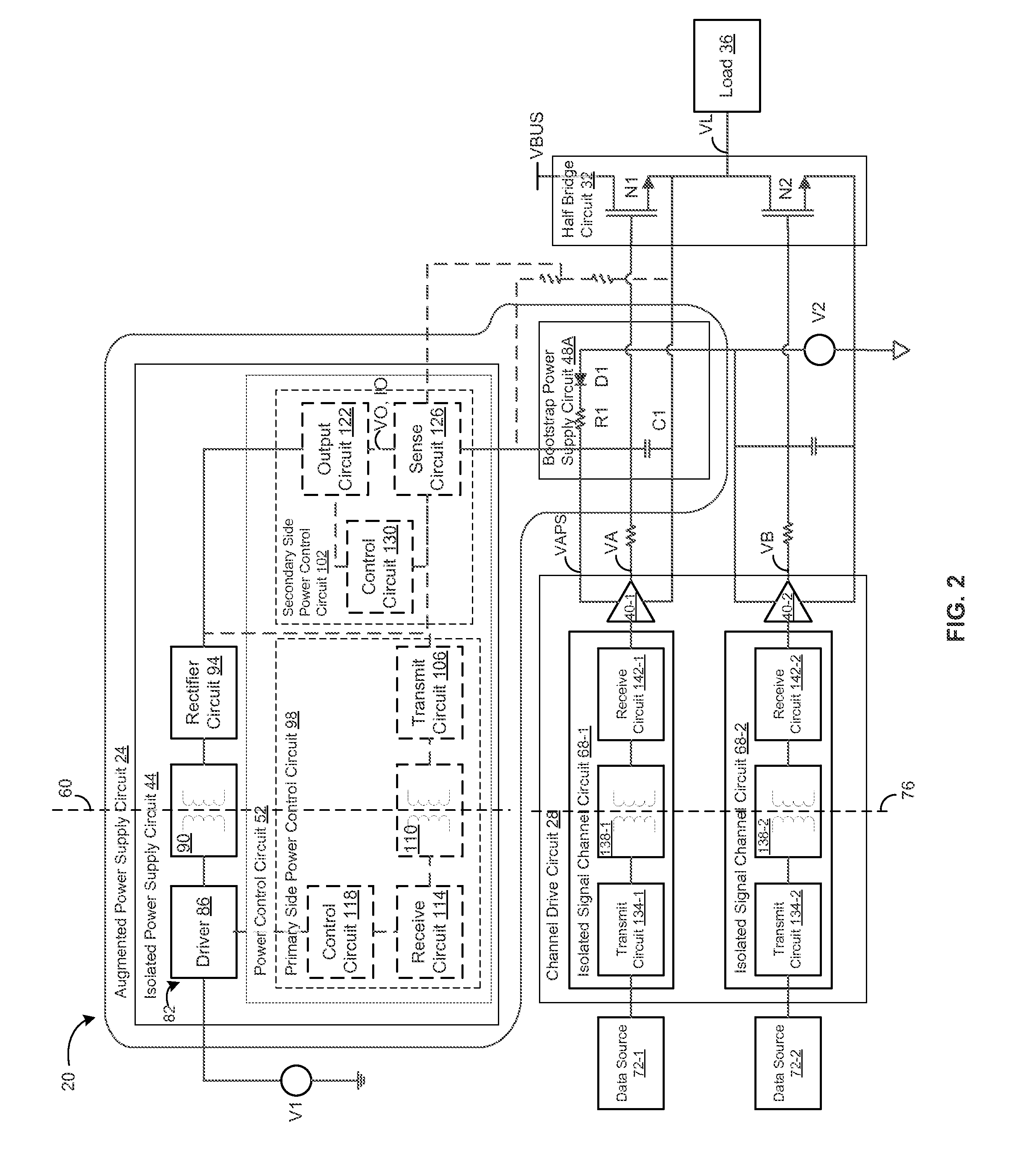
[0028]An embodiment of a power supply circuit to generate a supply voltage for a gate driver circuit can include an isolated power supply circuit to receive a first voltage in a first isolated system and provide power to a cyclic charging power supply circuit, the cyclic charging power supply circuit providing a supply voltage to the gate driver circuit in a second isolated system, the isolated power supply circuit providing the power to the cyclic charging power supply circuit while the gate driver circuit drives a transistor in an on state.

[0029]The isolated power supply circuit can include a control circuit to regulate the power provided so as to maintain or increase the supply voltage provided by the cyclic charging power supply circuit while the gate driver circuit drives the transistor in the on state. The control circuit may regulate the power supplied to maintain or increase the supply voltage while the gate driver drives the transistor in the on state by one or more of: lim...


PUM


Abstract

An embodiment of a power supply circuit to generate a supply voltage for a gate driver circuit can include an isolated power supply circuit to receive a first voltage in a first isolated system and provide power to a cyclic charging power supply circuit, the cyclic charging power supply circuit providing a supply voltage to the gate driver circuit in a second isolated system, the isolated power supply circuit providing the power to the cyclic charging power supply circuit while the gate driver circuit drives a transistor in an on state. The isolated power supply circuit can include a control circuit to regulate the power provided to maintain or increase the supply voltage while the gate driver circuit drives the transistor in an on state. The power supply circuit can also include the cyclic charging power supply circuit to receive a second voltage in the second isolated system and provide the supply voltage to the gate driver circuit. The cyclic charging power supply circuit can include one or more of a bootstrap power supply circuit or a charge pump power supply circuit.

Description

BACKGROUND INFORMATION[0001]Load driving circuits are used to drive loads in a variety of applications, such as within polyphase systems to drive electric motors. Many such load driving applications necessitate galvanic or other forms of isolation between the load system and another system delivering power, control and data inputs. Isolation is typically necessitated for a variety of reasons, including safety and reliability concerns associated with higher voltage levels present in the load system.[0002]In one form, a load driving circuit can include a half bridge circuit having a pair of NMOS power transistors connected to the load at respective source and drain terminals to provide corresponding high and low side driving. Using NMOS transistors to provide both high and low side driving can be advantageous due to the typically lower on resistance, higher power capability, and faster switching of NMOS transistors in comparison to PMOS transistors. However, using NMOS transistors to ...

Claims


Application Information

Patent Timeline
Patent Type & Authority Applications(United States)
IPC IPC(8): H03K17/687H02M1/088
CPCH02M1/088H03K17/687H02M1/08H02M1/0006
Inventor RICHARDSON, KENNETH G.SCHNELL, RYAN
Owner ANALOG DEVICES INC
Learn More