Joint structure and power steering device

a joint structure and power steering technology, applied in mechanical devices, couplings, transportation and packaging, etc., can solve the problems of excessive torque and damage to the elastic member, and achieve the effect of high durability

Active Publication Date: 2016-05-26
HITACHI ASTEMO LTD
View PDF3 Cites 9 Cited by
  • Summary
  • Abstract
  • Description
  • Claims
  • Application Information

AI Technical Summary

Benefits of technology

[0019]The joint structure and the power steering device discussed above make the rotational force being transmitted increase gradually, and are higher in durability.

Problems solved by technology

In this configuration, torque is repeatedly input to the elastic member, resulting in an excessive level of torque, and there is a possibility of damage to the elastic member.

Method used


Image

  • Joint structure and power steering device
  • Joint structure and power steering device
  • Joint structure and power steering device

Examples


first embodiment

[0038]A first embodiment of the present invention will be described with reference to FIG. 1 to FIG. 8.

[0039]>

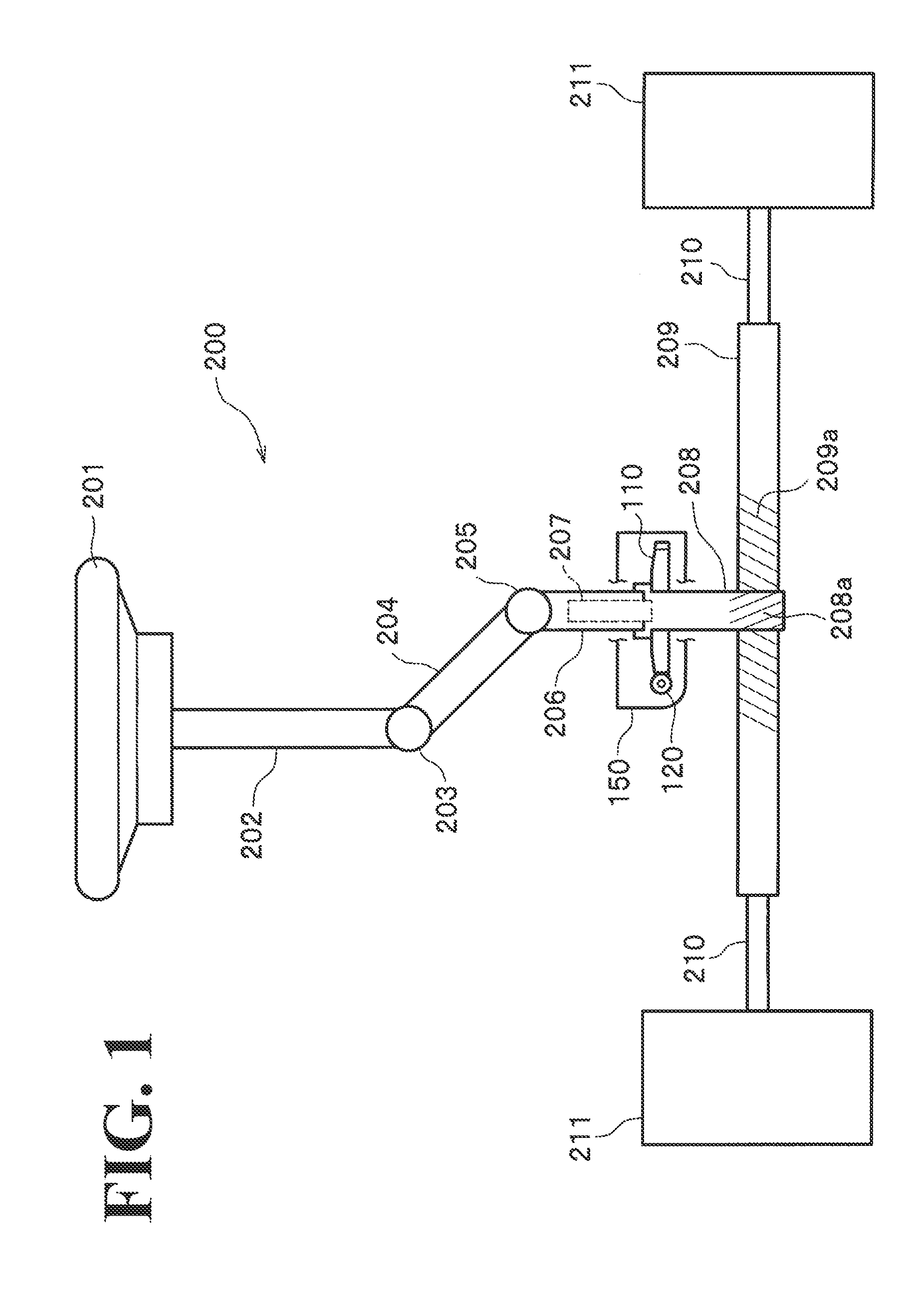
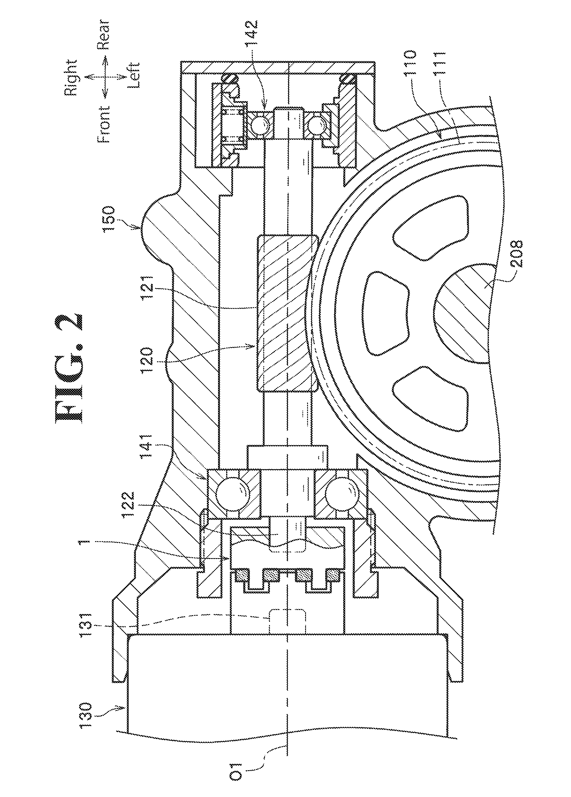
[0040]An electric power steering device 200 is of the pinion-assist type, in which assisting force (aid force) is input to a pinion shaft 208.

[0041]The electric power steering device 200 includes: a steering wheel 201, which is operated by a driver; a steering shaft 202 (steering column), which rotates together with the steering wheel 201; an intermediate shaft 204, which is connected to the steering shaft 202 through a first universal joint 203; an input shaft 206, which is connected to the intermediate shaft 204 through a second universal joint 205; a pinion shaft 208, which is connected to the input shaft 206 through a torsion bar 207 and provided with a pinion 208a, which is formed at the lower end of the pinion shaft 208; and a rack shaft 209, which includes a rack 209a, which is engaged with the pinion 208a. Both ends of the rack shaft 209 are connected to front wheels...

second embodiment

[0099]Next, a second embodiment of the present invention will be described with reference to FIG. 9 to FIG. 11. The following description will focus on those respects different from the first embodiment.

[0100]>

[0101]A joint structure 1A according to the second embodiment includes a first engagement member 10A, the second engagement member 20, and an elastic member 30A.

[0102]

[0103]The first engagement member 10A includes the first body 11 and four first engagement claws that extend rearward from the first body 11 and that are disposed at equal intervals in the circumferential direction. Here, for convenience of description, the four first engagement claws will be referred to as a first engagement claw 15A, a first engagement claw 15B, a first engagement claw 15A, and a first engagement claw 15B in the circumferential direction.

[0104]

[0105]A circumferential length (width) of the first engagement claw 15A and the first engagement claw 15B is uniform in the axial direction, instead of b...

third embodiment

[0120]Next, a third embodiment of the present invention will be described with reference to FIG. 12 to FIG. 13. The following description will focus on those respects different from the first embodiment.

[0121]>

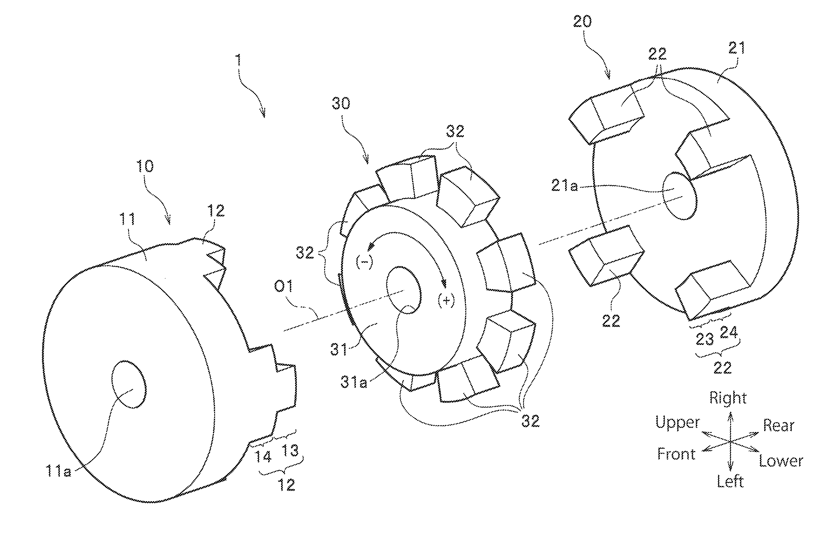
[0122]A joint structure 1B according to the third embodiment includes a first engagement member 10B, a second engagement member 20B, and four elastic members 30B.

[0123]

[0124]The first engagement member 10B includes the first body 11 and four first engagement claws 16, which extend from the first body 11 toward the second engagement member 20B. The four first engagement claws 16 are disposed at equal intervals in the circumferential direction.

[0125]

[0126]The second engagement member 20B includes the second body 21 and four second engagement claws 25, which extend from the second body 21 toward the first engagement member 10B. The four second engagement claws 25 are disposed at equal intervals in the circumferential direction.

[0127]

[0128]At an intermediate position in the axial ...


PUM


Abstract

A joint structure includes first and second engagement members, and an elastic member. The first engagement member includes a first body and a first engagement claw. The second engagement member includes a second body and a second engagement claw. The elastic member is disposed between the first and second engagement portions in a circumferential direction. When a relative rotation angle between the first and second engagement members is less than a predetermined angle, the first and second engagement claws are not in direct contact with each other in the circumferential direction, and a rotational force is transmitted through the elastic member while the elastic member is being elastically deformed. When the relative rotation angle is equal to the predetermined angle, the first and second engagement claws are in direct contact with each other in the circumferential direction.

Description

CROSS REFERENCE TO RELATED APPLICATION[0001]This is a continuation of International Application No. PCT / JP2013 / 071676 filed on Aug. 9, 2013, the entire disclosure of which is incorporated herein by reference.BACKGROUND[0002]1. Technical Field[0003]The present invention relates to a joint structure and a power steering device.[0004]2. Related Art[0005]Electric power steering devices are known to use electric motors to assist (aid) steering force. Known types of assisting methods include pinion-assist type, double pinion-assist type, rack-assist type, and column-assist type.[0006]For example, the pinion-assist type includes: a worm wheel fixed to a pinion shaft; and a worm engaged with the worm wheel and rotatable by a motor. A configuration oftentimes used to connect the output shaft of the motor (motor shaft) and the worm to each other is such a configuration that a coupling integrally molded or press-fitted to the motor shaft and having a spline hole is spline-connected to a spline...

Claims


Application Information

Patent Timeline
Patent Type & Authority Applications(United States)
IPC IPC(8): F16D3/50B62D3/10F16D3/02B62D5/04
CPCF16D3/50F16D3/02B62D3/10B62D5/0421F16D3/12F16D3/66F16D3/68B62D5/0409
Inventor KOGURE, AKIHIRO
Owner HITACHI ASTEMO LTD
Why Eureka
Try Eureka