Ventilation system for bathroom

a technology for ventilation systems and bathrooms, applied in ventilation systems, lighting and heating apparatus, heating types, etc., can solve the problems of unable to respond, simply exhausting the air from the bathroom, rendering ventilation difficult, etc., to achieve rapid air circulation, facilitate use, and remove the moisture of the walls of the bathroom quickly

Active Publication Date: 2016-05-26
KWON WOO DEUK
View PDF9 Cites 4 Cited by
  • Summary
  • Abstract
  • Description
  • Claims
  • Application Information

AI Technical Summary

Benefits of technology

[0015]The bathroom ventilation system according to the present invention, as described above, provides the following effects.
[0016]The intake of air in the bathroom and supply of external air are simultaneously performed through the bi-directional ventilation tube 300. Accordingly, even in the airtight state where the bathroom door stands closed, more loads are prevented from being applied to the air exhausting fan 250, and air circulation is swiftly done. Therefore, the bathroom may remain at a pleasant atmosphere.
[0017]Formation of the downwardly-inclined guiding plate 330 along the periphery of the air intake part 320 enables the air discharged from the air exhausting part 310 to flow evenly passing the walls of the bathroom, thus quickly removing the moisture of the walls of the bathroom.
[0018]The intake adjusting member 400 is provided at a lower side of the air intake part 320 to move up and down. Accordingly, the user may adjust the amount of air exhausted from the inside of the bathroom and from around the toilet 10, thus allowing for easier use.
[0019]The internal air traveling tube 200 includes the second exhaust pathway 220 connected with the toilet 10. Accordingly, the odors around the toilet 10 may be quickly drawn out through the toilet 10 without passing through the inside of the bathroom, thus minimizing germ proliferation. Therefore, the bathroom may remain clean.
[0020]The adjusting plate 240 is provided in the third exhaust pathway 230 to be movable toward the first exhaust pathway 210 and the second exhaust pathway 220 depending on air intakes, thus reducing occurrence of a vortex in the joining section 231 while preventing the air sucked through the second exhaust pathway 220 from flowing back to the first exhaust pathway 210.

Problems solved by technology

However, such air exhausting facility simply exhausts air from the bathroom and cannot respond to the satisfaction when the bathroom door remains closed, i.e., in the airtight bathroom.
In other words, although for ventilation an air intake should be the same as the amount of air exhaust, the air intake in the door-closed state fails to reach the amount of air exhaust, thus rendering ventilation difficult.

Method used


Image

  • Ventilation system for bathroom
  • Ventilation system for bathroom
  • Ventilation system for bathroom

Examples


Embodiment Construction

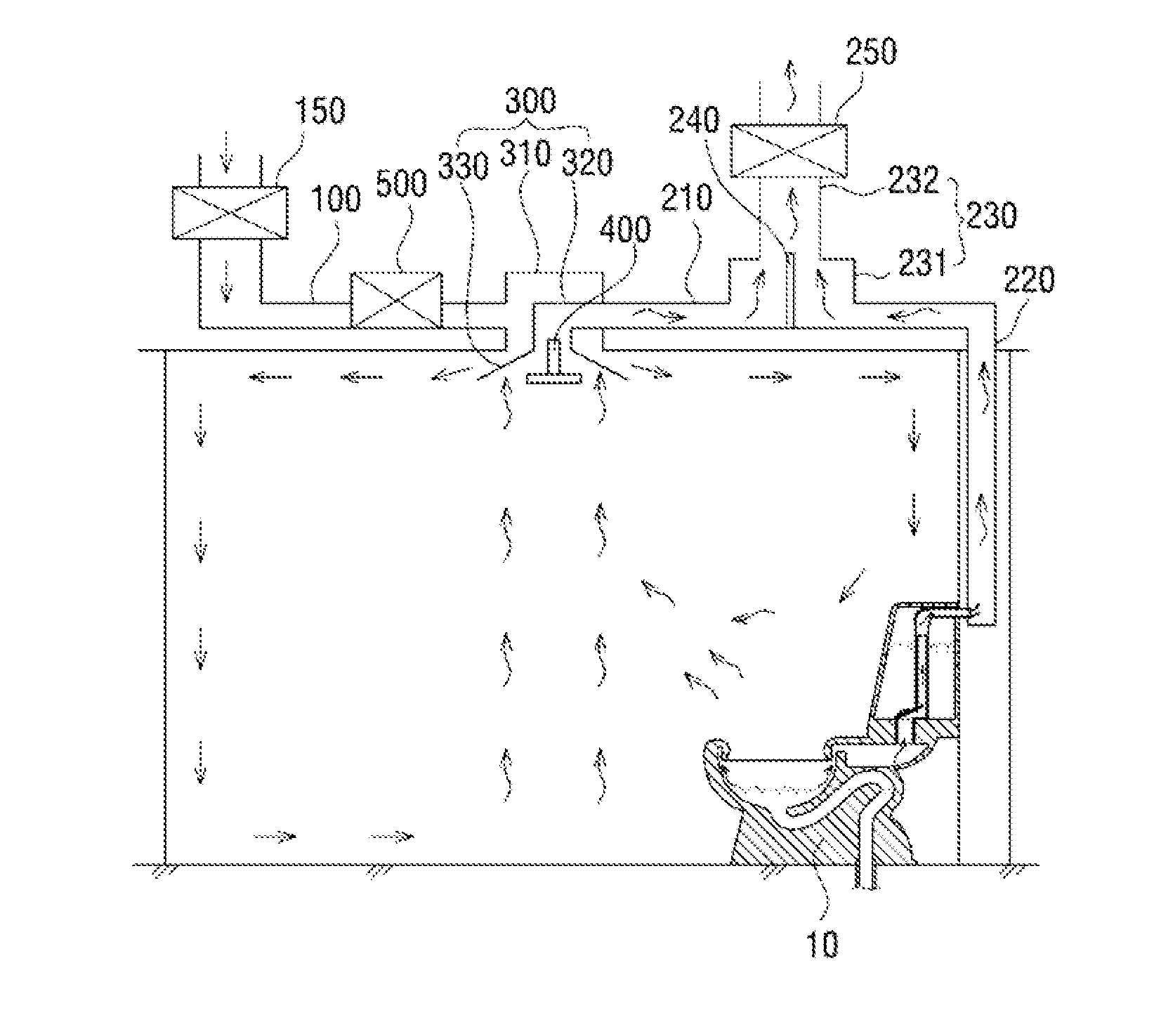
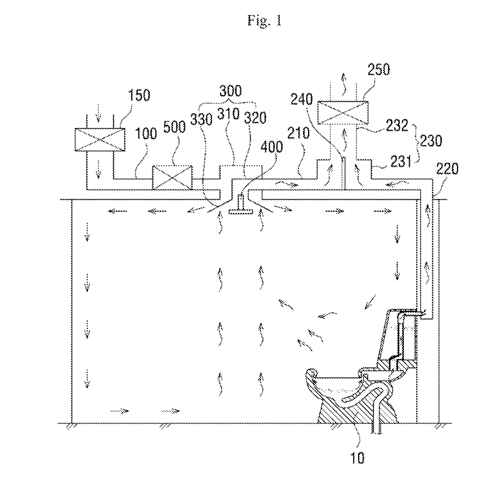
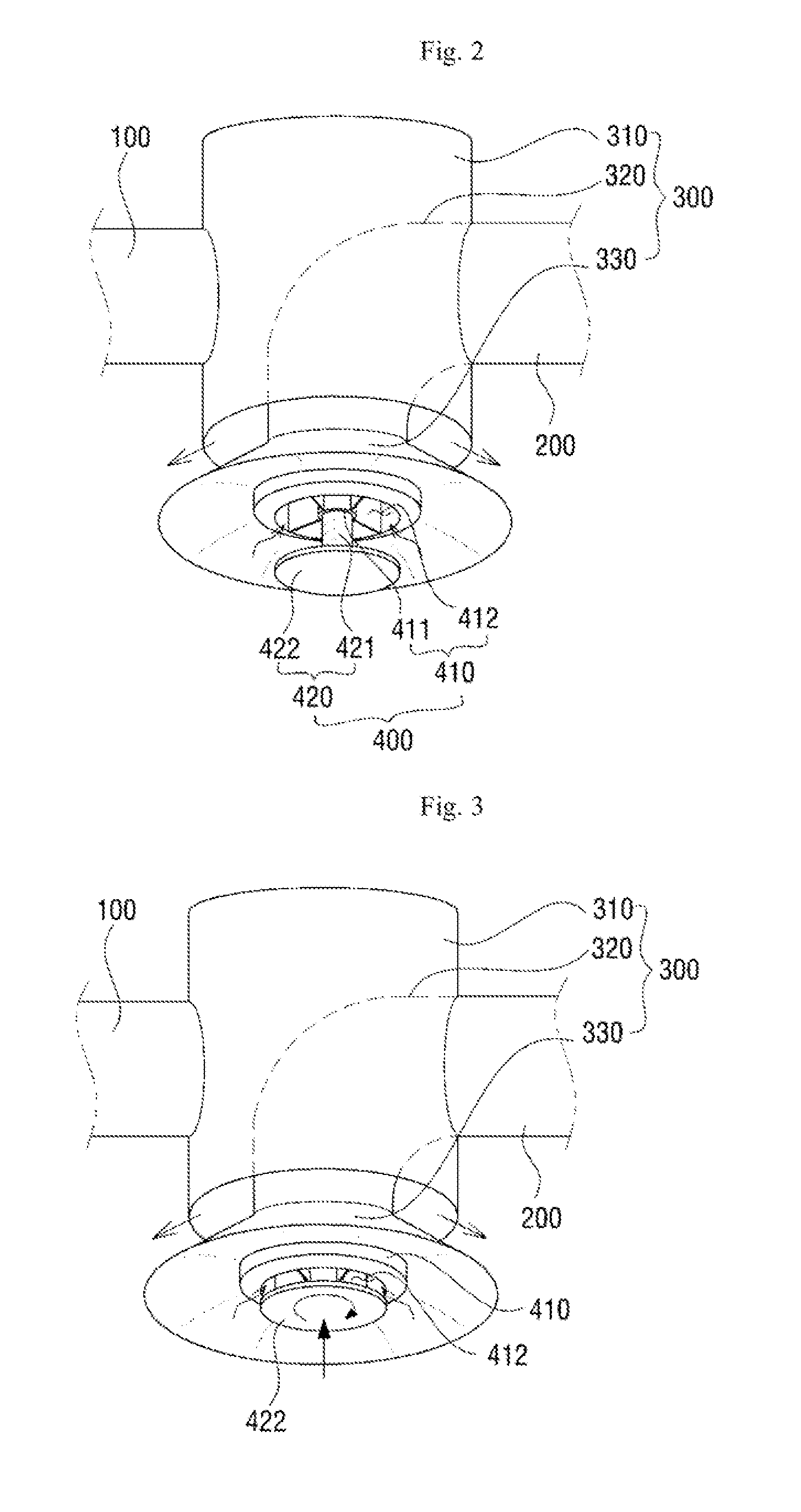
[0026]FIG. 1 is a view illustrating a side cross-sectional structure of a bathroom ventilation system according to an embodiment of the present invention. FIG. 2 is a perspective view illustrating a bi-directional ventilation tube 300 of a bathroom ventilation system according to an embodiment of the present invention. FIG. 3 is a view illustrating an operation state of an intake adjusting member 400 of a bathroom ventilation system according to an embodiment of the present invention. FIG. 4 is a perspective view illustrating a third exhaust pathway 230 of a bathroom ventilation system according to an embodiment of the present invention. FIG. 5 is an expanded view illustrating a side cross-sectional structure of a second exhaust pathway 220 and a toilet 10 of a bathroom ventilation system according to an embodiment of the present invention.

[0027]As shown in FIGS. 1 to 5, according to an embodiment of the present invention, the bathroom ventilation system includes an external air tra...


PUM


Abstract

The present invention aims to provide a bathroom ventilation system having a bi-directional ventilation tube that exhausts internal air to the outside while supplying external air into the bathroom to allow for quick ventilation in the bathroom and to draw toilet odors as well as air in the bathroom out of the bathroom through an internal air traveling tube, thereby minimizing occurrence of odors.To achieve the above object, according to the present invention, a ventilation system for a bathroom comprises: an external air traveling tube 100 provided at an upper side of a ceiling panel of the bathroom and having an air intake fan 150 that takes air in from an outside and moves the taken-in air to an inside of the bathroom; an internal air traveling tube 200 provided at the upper side of the ceiling panel of the bathroom and having an air exhausting fan 250 that draws air from the inside of the bathroom to the outside; and a bi-directional ventilation tube 300 provided at a ceiling of the bathroom, the bi-directional ventilation tube 300 including an air exhausting part 310 having a side connected with the external air traveling tube 100 and another side connected with the inside of the bathroom and an air intake part 320 having a side connected with the internal air traveling tube 200 and another side connected with the inside of the bathroom.

Description

TECHNICAL FIELD[0001]The present invention relates to a ventilation system for a bathroom, and particularly, to a ventilation system for a bathroom that uses a blower to forcedly discharge air out of the bathroom to refresh the inside the bathroom.BACKGROUND ART[0002]In general, an apartment building, office building or other human life space has a bathroom(s). In the past, the bathroom was placed at a location isolated from the living space to treat the human excreta. However, a recent trend is towards the bathroom being housed inside the living space as the apartment is favored as a dwelling.[0003]Following such trend, the toilet and basin installed in the bathroom goes on evolving for more sanitation. Further, a change in function of the bathroom from a mere space to treat human waste to a multi-functional room for bathing and makeup led to people staying longer in the bathroom, and the waste treatment space is thus in the trend of being equipped with higher-class facilities.[000...

Claims


Application Information

Patent Timeline
Patent Type & Authority Applications(United States)
IPC IPC(8): F24F7/08F24F13/10F24F7/10
CPCF24F7/08F24F13/10F24F7/10E03D9/04F24F2221/18E03D9/05F24F7/007F24F7/025
Inventor KWON, WOO DEUK
Owner KWON WOO DEUK
Why Eureka
Try Eureka