Plastic beehive

a beehive and beehive technology, applied in the field of beehives, can solve the problems of not being able to obtain the appropriate conditions for bees, occupying a lot of space in the beehive, and achieving the effect of effective air circulation in the beehiv

Active Publication Date: 2010-08-12
YILDIRIM MUZAFFER
View PDF11 Cites 1 Cited by
  • Summary
  • Abstract
  • Description
  • Claims
  • Application Information

AI Technical Summary

Benefits of technology

[0011]On top of the hive, there is a top cover. The louvers which are located on the top cover enable air inlet. The ventilation channels that are present on the lower cover and the louvers that are present on the top cover enable the realization of air circulation in the hive effectively.

Problems solved by technology

The beehives take up a lot of space by volume and this causes carrying problems.
In addition the ventilation and the heat isolation of the beehives are not on desired level and this leads to not being able to obtain the appropriate conditions for the bees.

Method used


Image

  • Plastic beehive
  • Plastic beehive
  • Plastic beehive

Examples


Embodiment Construction

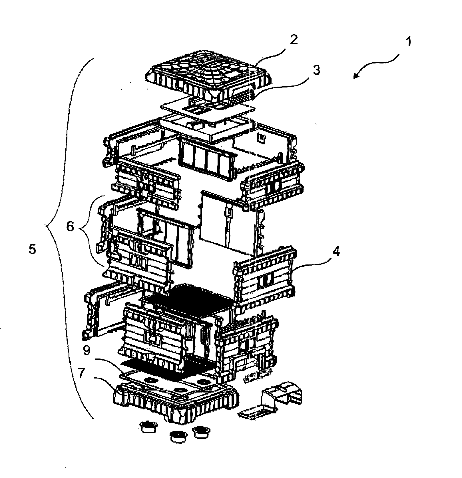
[0012]The beehive realized to fulfill the objective of the present invention is illustrated in the accompanying figures, in which:

[0013]FIG. 1 is the exploded view of the inventive hive.

[0014]FIG. 2 is the exploded view of a single-layered embodiment of the inventive hive.

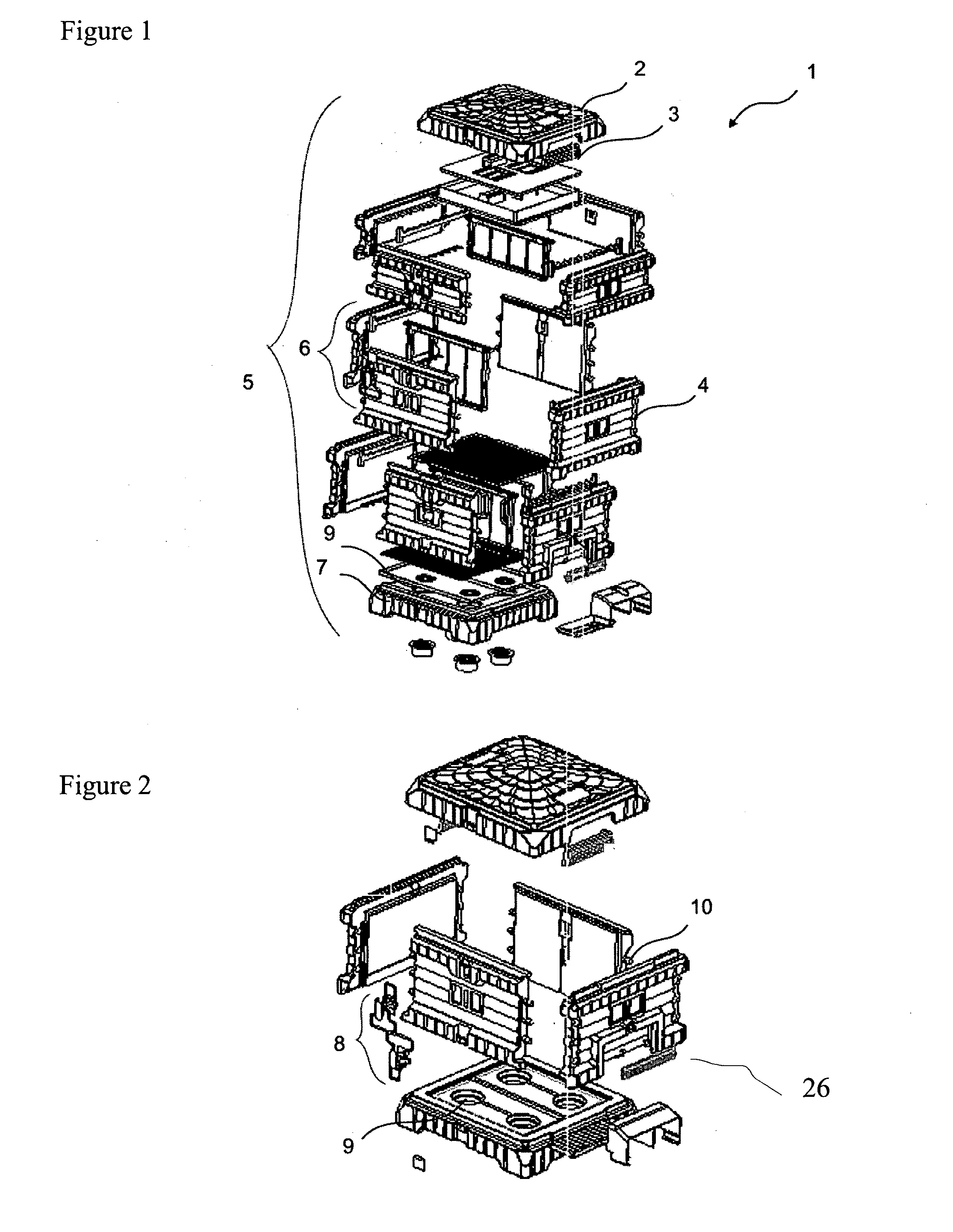
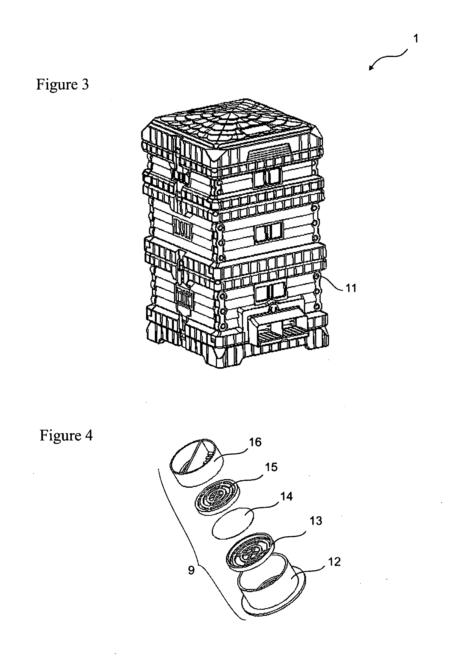
[0015]FIG. 3 is the perspective view of the hive.

[0016]FIG. 4 is the exploded view of the ventilation channels.

[0017]FIG. 5 is the exploded view of the inner parts of the hive.

[0018]FIG. 6 is the perspective view of the locking latch.

[0019]FIG. 7 is the perspective view of the walls.

[0020]FIG. 8 is the perspective view of an embodiment of the hive wherein the walls of them are fastened to each other with screws.

[0021]FIG. 9 is the perspective view of the hive entrance while the pollen trap is being attached.

[0022]FIG. 10 is the exploded view of the pollen trap.

[0023]FIG. 11 is the top and side view of the queen bee section filter.

[0024]The parts shown in the figures are individually numbered, where the numbers refe...


PUM


Abstract

The present invention relates to demounted beehives wherein the air circulation is realized effectively and the heat isolation is enhanced. The beehive essentially comprises one or more body (5), a top cover (2) and also a lower cover (7).

Description

FIELD OF THE INVENTION[0001]The present invention relates to demounted beehives wherein the air circulation is realized effectively and the heat isolation is enhanced.BACKGROUND OF THE INVENTION[0002]The beehives known in the state of the art are produced from wood, metal or plastic. The beehives take up a lot of space by volume and this causes carrying problems. In addition the ventilation and the heat isolation of the beehives are not on desired level and this leads to not being able to obtain the appropriate conditions for the bees.[0003]In French patent document No. FR2540339 which is within the state of the art, a beehive wherein the walls are fastened to each other by shrink-fit without requiring rawlplug is mentioned.[0004]In Greek patent document No. GR1005104 which is within the state of the art, a hive wherein the walls are fastened to each other by shrink-fit is mentioned. The walls which have been engaged to each other by shrink-fit in this hive provide the isolation so ...

Claims


Application Information

Patent Timeline
Patent Type & Authority Applications(United States)
IPC IPC(8): A01K47/06
CPCA01K47/06A01K47/00
Inventor YILDIRIM, MUZAFFER
Owner YILDIRIM MUZAFFER
Why Eureka
Try Eureka