Circuit and method of providing a stable display for eddy current instruments

a technology of eddy current inspection and circuit, which is applied in the direction of instruments, scientific instruments, measurement devices, etc., can solve the problems of inspectors in the field having to deal with a “, analyst may accidentally pass over some flaws, etc., and achieve the effect of reducing the risk of accidents

Active Publication Date: 2016-05-26
OLYMPUS AMERICA
View PDF6 Cites 3 Cited by
  • Summary
  • Abstract
  • Description
  • Claims
  • Application Information

AI Technical Summary

Benefits of technology

[0009]It is a general object of the present disclosure to provide a signal processing and plotting method that yields a controlled and systematic display of the response of an eddy current differential probe inspecting the interior of a cylindrical cavity.
[0010]It is further an object of the present disclosure to control phase independently from low and high pass filter parameters. One implementation is to use a Hilbert transform with which a 90 degree phase shift is intrinsic and definitive, and an inspector can easily switch from an ideal differential probe signal to a phase-shifted differential signal. Once optimized for application, high and low pass filter frequency settings can be linked to the RPM setting of the rotary bolt scanner to provide a reasonable variation range due to probe friction in the hole, while maintaining a largely constant displayed signal size.
[0011]It is further another object of the present disclosure to use a Hilbert transform to phase shift the signals at the “flat” range of frequency response of a high pass filter, so that motor speed variation does not cause an err

Problems solved by technology

When using the instrument configured in this way, the analyst may accidentally pass over some flaws because they produce a display pattern very similar to the standard crack “figure 8” but flipped over in such a way that they appear very similar.
One pro

Method used


Image

  • Circuit and method of providing a stable display for  eddy current instruments
  • Circuit and method of providing a stable display for  eddy current instruments
  • Circuit and method of providing a stable display for  eddy current instruments

Examples


Embodiment Construction

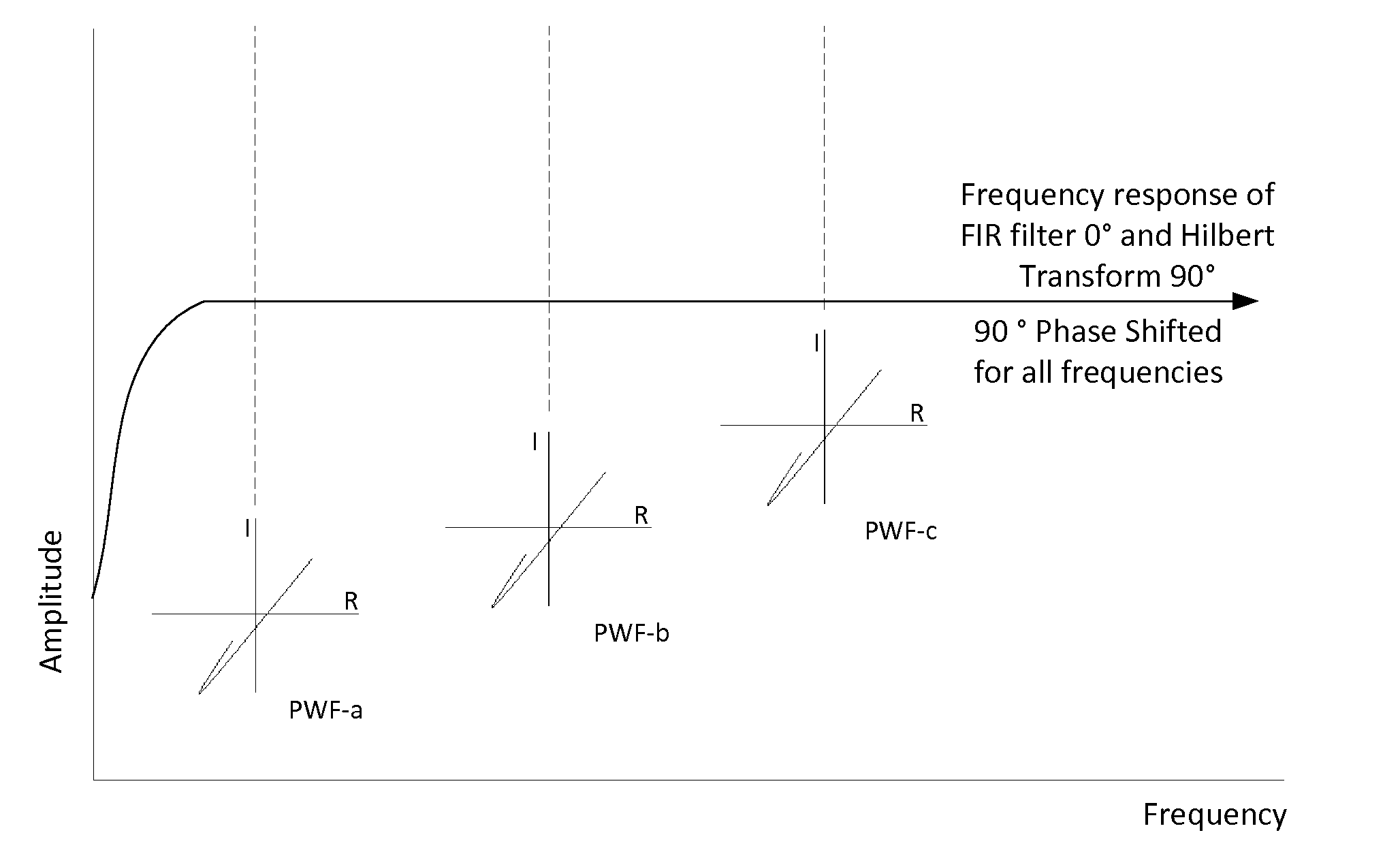
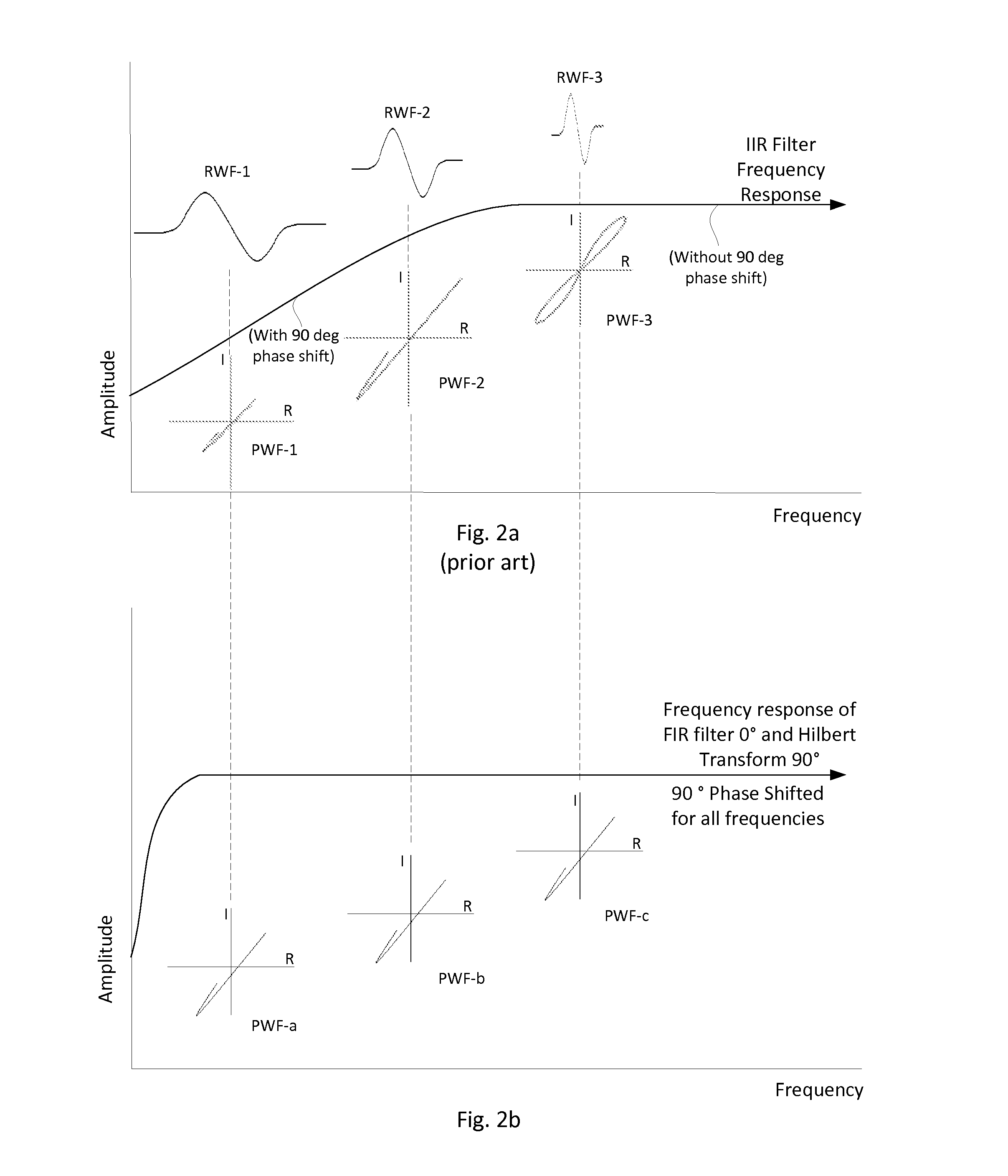
[0018]It should be noted that all functions herein described as a digital circuit can also be implemented using analog circuits. An analog method has been practical for many years, and is not an improvement made possible only by digital methods, and should fall under the scope of the present disclosure. It should also be noted that the core concept of this patent is the inclusion of a wide frequency range phase shift filter. The use of a Hilbert transform can be directly implemented as shown in present disclosure, or it can be done indirectly by the use of other frequency sensitive circuits used together to make a composite filter.

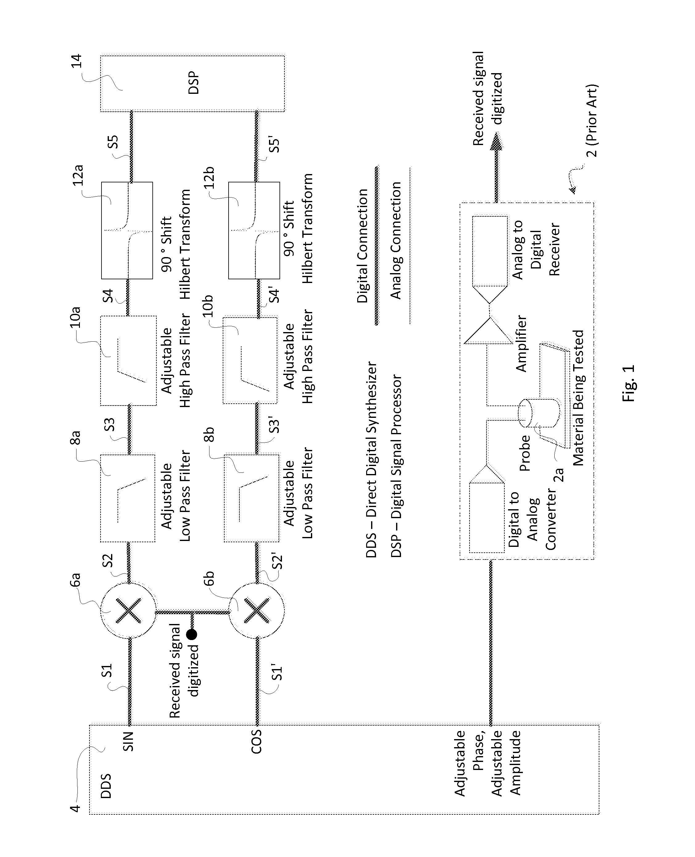
[0019]Referring to FIG. 1, an exemplary embodiment of the an eddy current front end circuitry 2 is used to digitize signal coming back from probe 2a which is attached to a rotary bolt hole scanner (not shown). The digitized signal is provided by circuitry 2.

[0020]The circuitry of the present disclosure comprises the front-end circuitry 2, a direct digital ...


PUM


Abstract

A rotary bolt hole eddy current inspection scanner using a differential eddy current probe, the circuitry of the scanner is embodied with a filtering circuit with three filters: FIR (Finite Impulse Response), a low pass filter, and a phase control filter (by means of a Hilbert transform). The result from a scan of a bolt hole is an output signal on an impedance plane exhibiting a “backwards 6” shape of stable size when the scanner changes its rotating rate significantly.

Description

FIELD OF THE INVENTION[0001]This invention relates to non-destructive testing and inspection (NDT / NDI), particularly to an improved signal processing circuitry of an eddy current inspection instrument with a rotary scanner implementation to achieve a stable display in a testing result.BACKGROUND OF THE INVENTION[0002]An eddy current probe uses an alternating current that flows through a wire coil and generates an oscillating magnetic field. If the probe and its magnetic field are brought close to a conductive material like a metal test piece, a circular flow of electrons known as an eddy current moves through the metal and generates its own magnetic field, which interacts with the coil and its field through mutual inductance.[0003]Changes in metal thickness or defects like near-surface cracking interrupt or alter the amplitude and pattern of the eddy current and the resulting magnetic field. This in turn affects the movement of electrons in the coil by varying the electrical impedan...

Claims


Application Information

Patent Timeline
IPC IPC(8): G01N27/90
CPCG01N27/902G01N27/9046G01N27/908
Inventor THOMAS, ANDREW
Owner OLYMPUS AMERICA
Why Eureka
Try Eureka