
Rack server system and power management method thereof

a server system and rack technology, applied in the field of rack server systems, can solve the problems of low conversion efficiency, increased load for the server, increased power consumption, etc., and achieve the effects of preventing the load exceeding the capacity reducing the load, and improving the conversion efficiency of the power supply uni

Inactive Publication Date: 2016-05-26
INVENTEC PUDONG TECH CORPOARTION +1
View PDF3 Cites 7 Cited by
  • Summary
  • Abstract
  • Description
  • Claims
  • Application Information

AI Technical Summary

Benefits of technology

The present invention is a system that detects the work number of servers to control the number of power supply units, which makes it possible to improve the conversion efficiency and extend the life of the power supply units. Additionally, the monitoring signal transmitted during server operation helps to automatically add more working power supply units to prevent loading beyond the units' capacity. These features make it easier to manage and control the power supply units.

Problems solved by technology

With the increasing of server's function, the loading for the servers also increases, and thus it has become an important management issue in present to check if the power supplied by the power supply unit can carry the whole rack server system.
However, because not all the servers are working except the rush hour, to fully turn on the power supply may result in the unnecessary power consumption and cause the problem of low conversion efficiency.
In addition, to turn on the power supply unit frequently may reduce the life of the power supply unit.
However, as the rush hour comes, more servers are started and the already turned on power supply units cannot carry the increasing number of working servers and thus the managing persons needs to manually turn on the power supply units.
Such operation is quite inconvenient to the managing persons and lacks efficiency.

Method used


Image

  • Rack server system and power management method thereof
  • Rack server system and power management method thereof
  • Rack server system and power management method thereof

Examples


Embodiment Construction

[0015]There are various embodiments of the rack server system provided in accordance with the present invention, which are not repeated hereby. Only a preferred embodiment is mentioned in the following paragraph as an example.

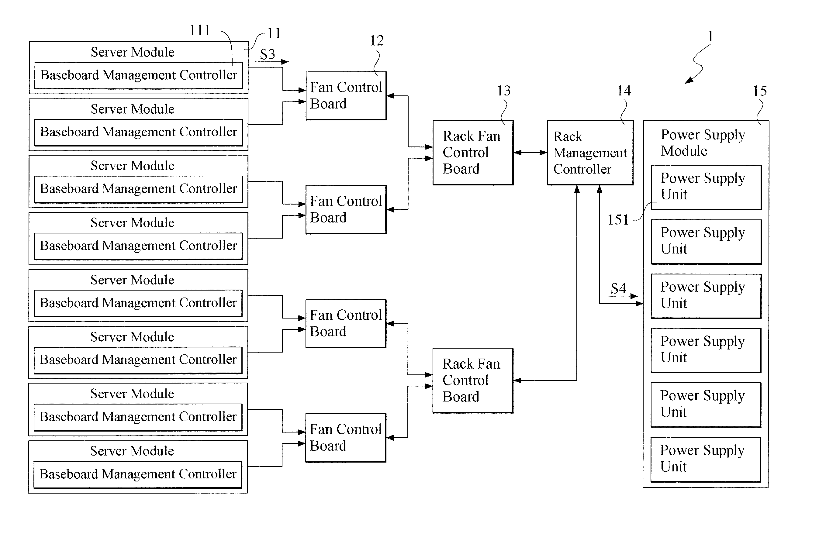
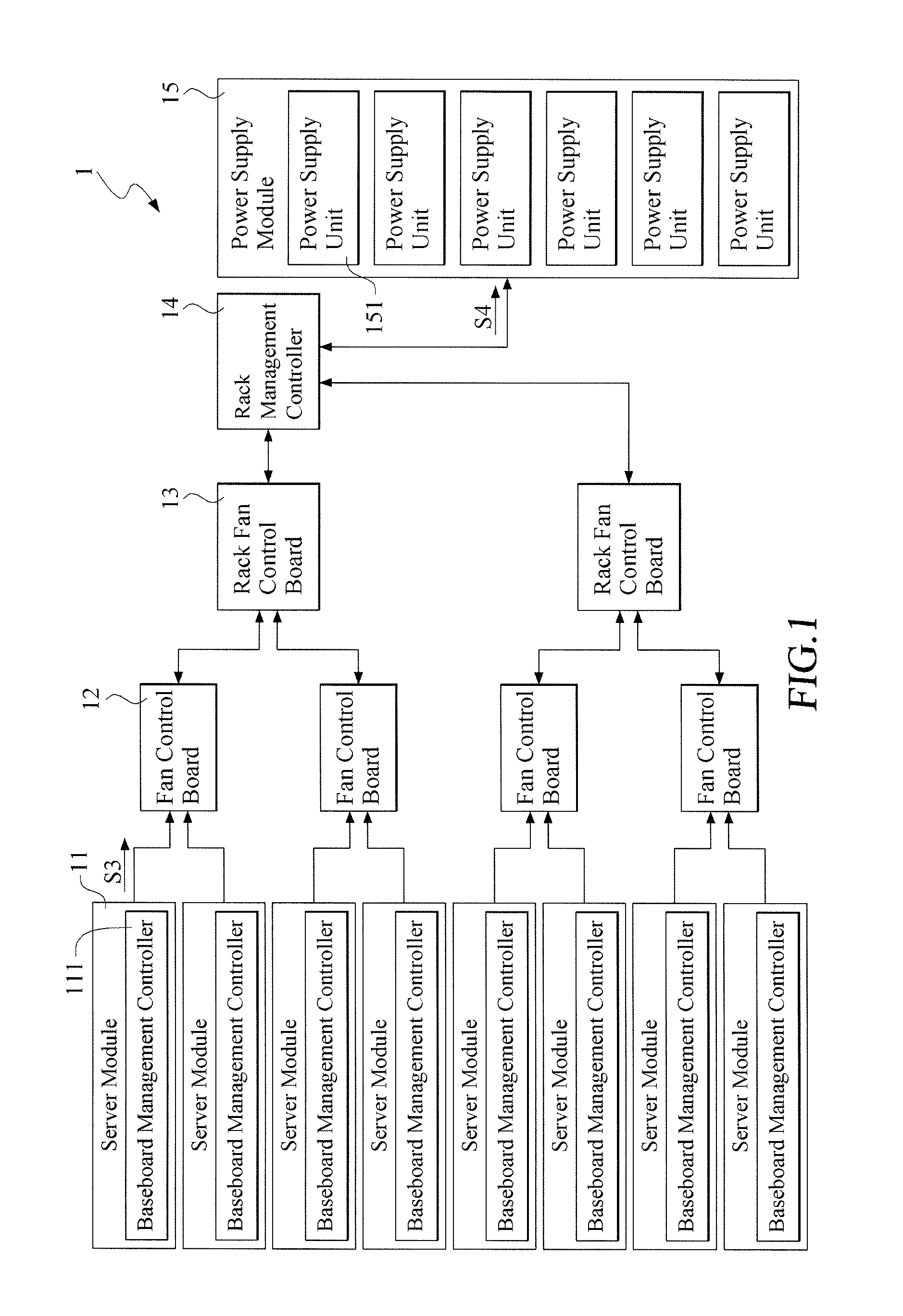
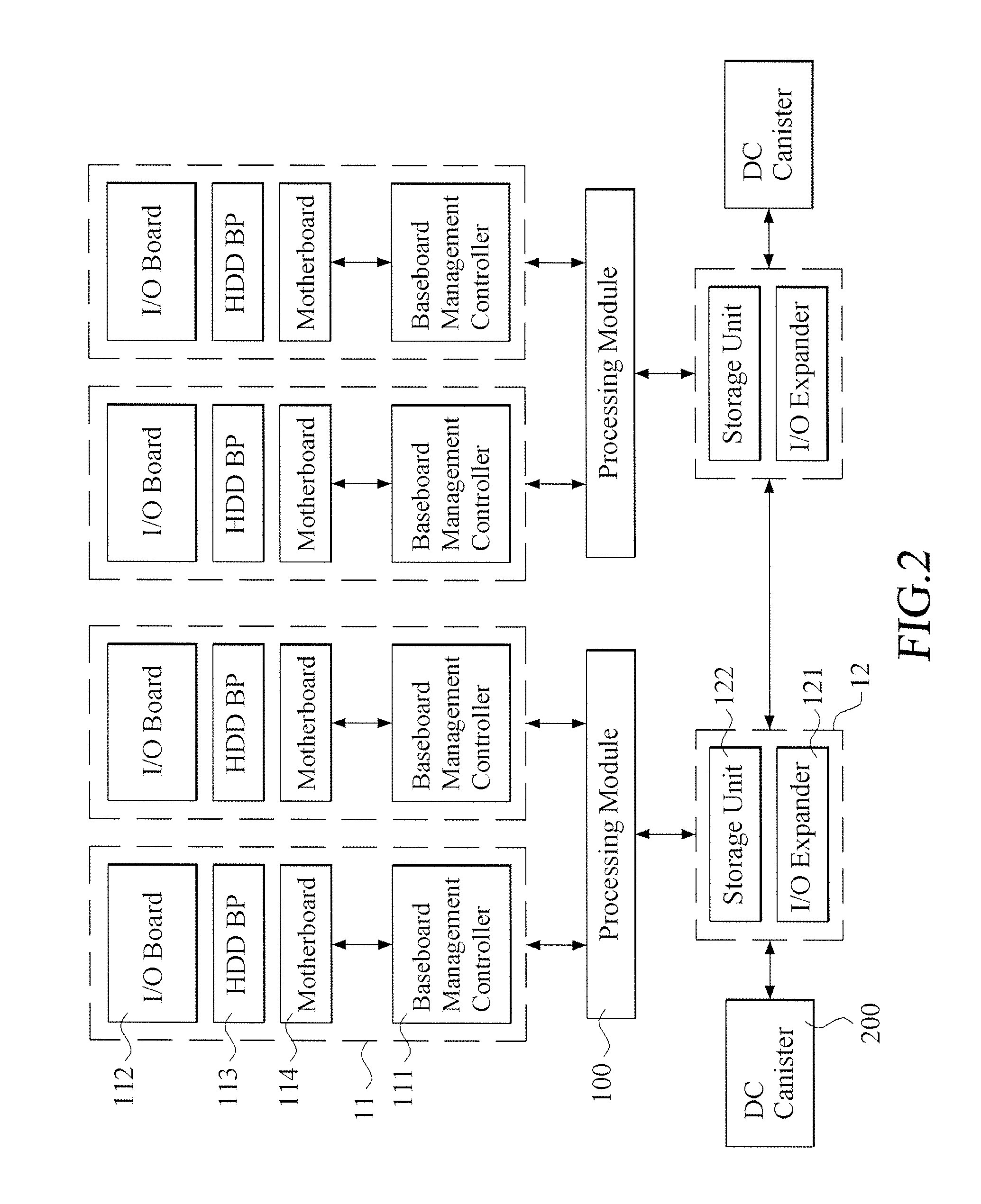
[0016]Please refer to FIGS. 1 to 3, wherein FIG. 1 is a block diagram showing the rack server system in accordance with a preferred embodiment of the present invention, FIG. 2 is a block diagram showing the server and the fan control board in accordance with a preferred embodiment of the present invention, and FIG. 3 is a flow chart showing the power management method in accordance with a preferred embodiment of the present invention. As shown, the rack server system 1 includes a plurality of server modules 11 (only one of them is labeled), a plurality of fan control boards (FCB) 12 (only one of them is labeled), a plurality of rack ran control board (RFCB) 13 (only one of them is labeled), at least a rack management controller (RMC) 14 (only one is shown in th...


PUM


Abstract

A rack server system and power management method is provided for automatically controlling work state of power supplies. The rack server system includes a plurality of servers, at least one rack management controller, and a power supply module. Each of the servers includes a baseboard management controller, which is configured to monitor a server information of the servers and transmits the server information to the rack management controller. The rack management controller calculates the server information to produce a sever work number so as to transmits a control signal including the sever work number to the power supply module. The power supply units are turned on by the power supply module as receiving the control signal.

Description

FIELD OF THE INVENTION[0001]The present invention is related to a rack server system, and more particularly related to a rack server system, which can control the number of working power supply units based on a sever work number.BACKGROUND OF THE INVENTION[0002]Attending with the progress of technology, network has played an indispensable role in our daily lives, and people are used to do the data communication through the network, such as the communication and interaction by using the social application or social networking websites. For the construction of network, a server is an important apparatus for providing network service. In general, a network system should include a plurality of servers for the purpose of computing a great amount of data.[0003]The above mentioned plurality of servers is usually disposed in a rack as a rack server system to facilitate management, and all the above mentioned servers are electrically connected with a fan and a power supply unit (PSU). With t...

Claims


Application Information

Patent Timeline
Patent Type & Authority Applications(United States)
IPC IPC(8): G06F1/32G06F1/20
CPCG06F1/20G06F1/3206H05K7/1458
Inventor CHEN, YUNG-YING
Owner INVENTEC PUDONG TECH CORPOARTION
Learn More