Ticket dispenser

a dispenser and ticket technology, applied in the field of ticket dispensers, can solve the problems of dispensers that require mechanical linkages complicated, require additional security features for ticket dispensing, and require mechanical linkages that are mechanically complex, so as to reduce the abrasion of the inner face, and enhance the reliability of ticket dispensing

Inactive Publication Date: 2016-06-02
FASTRAK RETAIL UK
View PDF4 Cites 1 Cited by
  • Summary
  • Abstract
  • Description
  • Claims
  • Application Information

AI Technical Summary

Benefits of technology

[0009]Advantageously, standing the tickets on the edge on the support platform enables the ticket to be dispensed by a low complexity mechanical dispensing mechanism. Further, the dispensing mechanism may be operable by depression of the dispensing control member a counter onto which the ticket dispenser may be mounted, thereby requiring a low complexity mounting arrangement.
[0032]The inner surface of the customer-facing side of the housing may be curved back towards the pack of tickets. Advantageously, curvature of the inner face enhances contact with the dispensing edge of the ticket being dispensed, thereby enhancing guiding of the ticket as it is dispensed. Further, curving the dispensing ticket back towards the pack may further enhance the maintenance of a straight second edge, to enhance the reliability with which the second edge is guided towards and passes through the dispensing slot, during dispensing.

Problems solved by technology

Disadvantageously, in such a ticket dispenser, the display face of the ticket to be dispensed does not face the customer and cannot be viewed by the customer prior to dispensing.
Also, although the ticket is conveniently dispensed towards the customer, the dispensing operation is not controlled by the retailer, consequently requiring additional security features for dispensing valuable tickets.
Further, such a dispenser is only suited to dispensing relatively rigid tickets in order that the dispensing edge aligns with the dispensing slot, and would risk jamming if the dispensing edge of a ticket should become buckled.
Yet further, the dispenser requires a mechanically complex mechanical linkage between the pivoting panel and the ticket ejector.

Method used


Image

  • Ticket dispenser
  • Ticket dispenser
  • Ticket dispenser

Examples


Embodiment Construction

[0056]In the described embodiment, like features have been identified with like numerals, albeit in some cases having one or more of suffix letters.

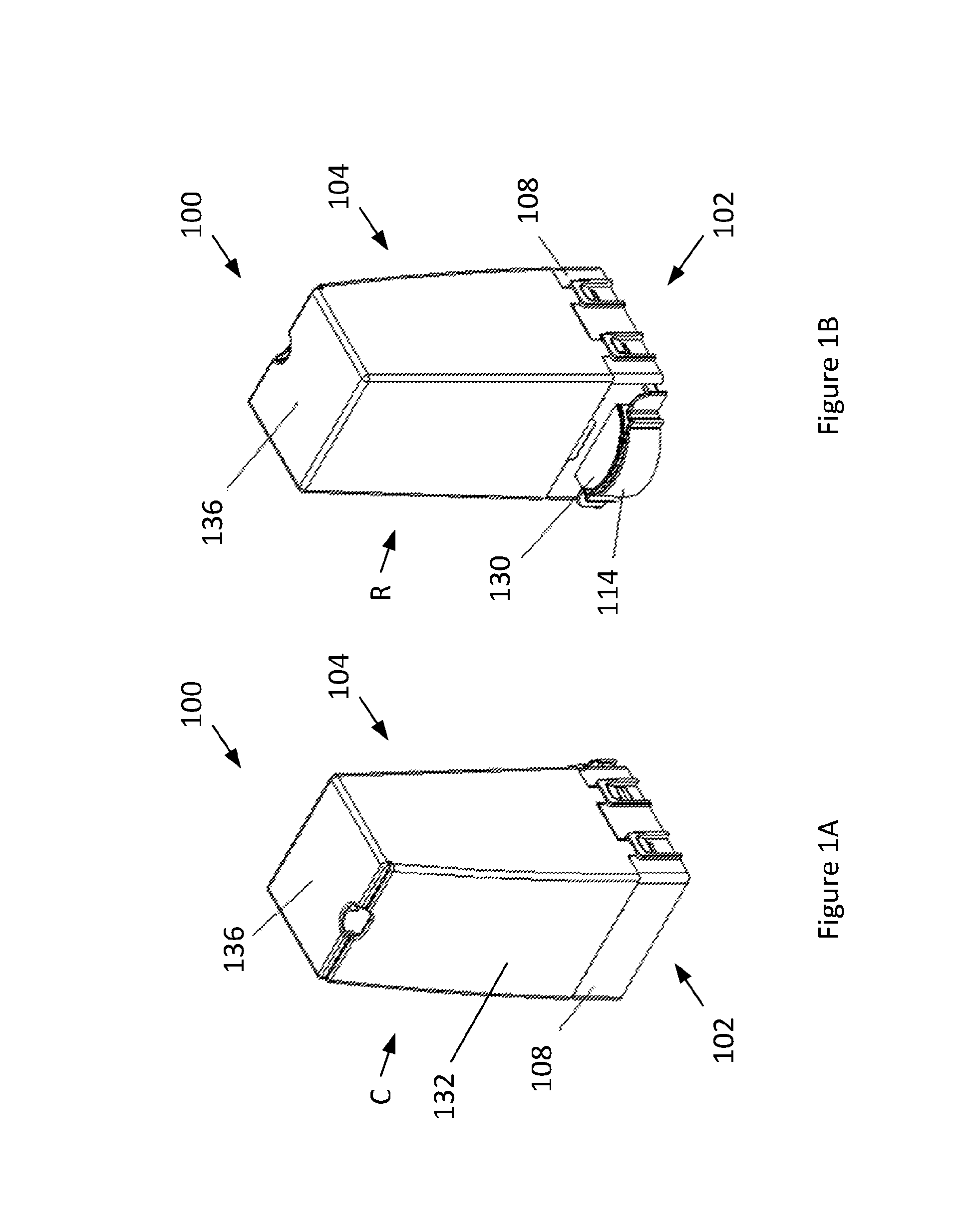
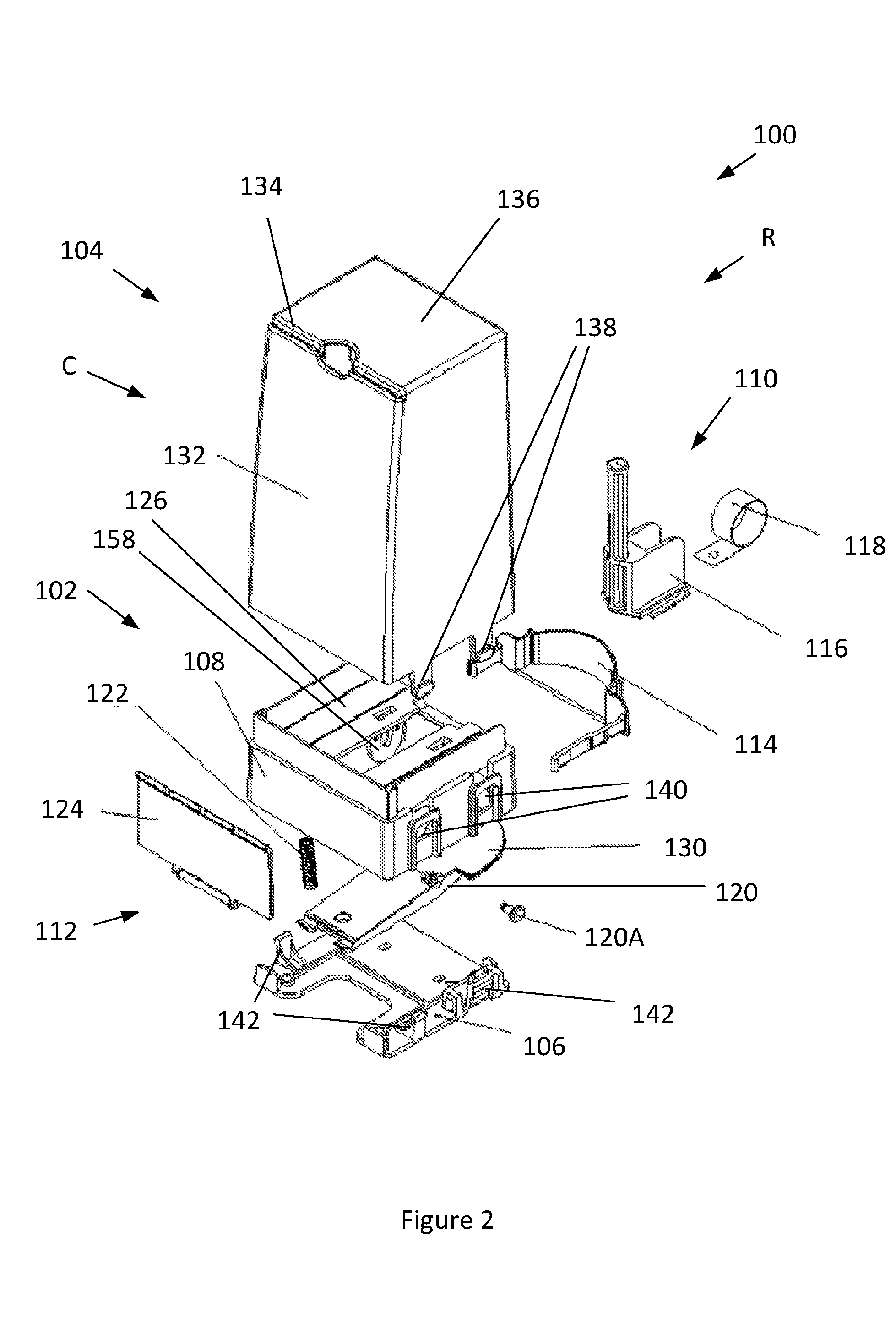
[0057]FIGS. 1A and 1B respectively show the fully assembled ticket dispenser 100 from a customer-facing side C and an opposed retailer-facing side R, FIG. 2 shows an exploded view of the ticket dispenser, and FIGS. 3A and 3B show partially disassembled views of the ticket dispenser.

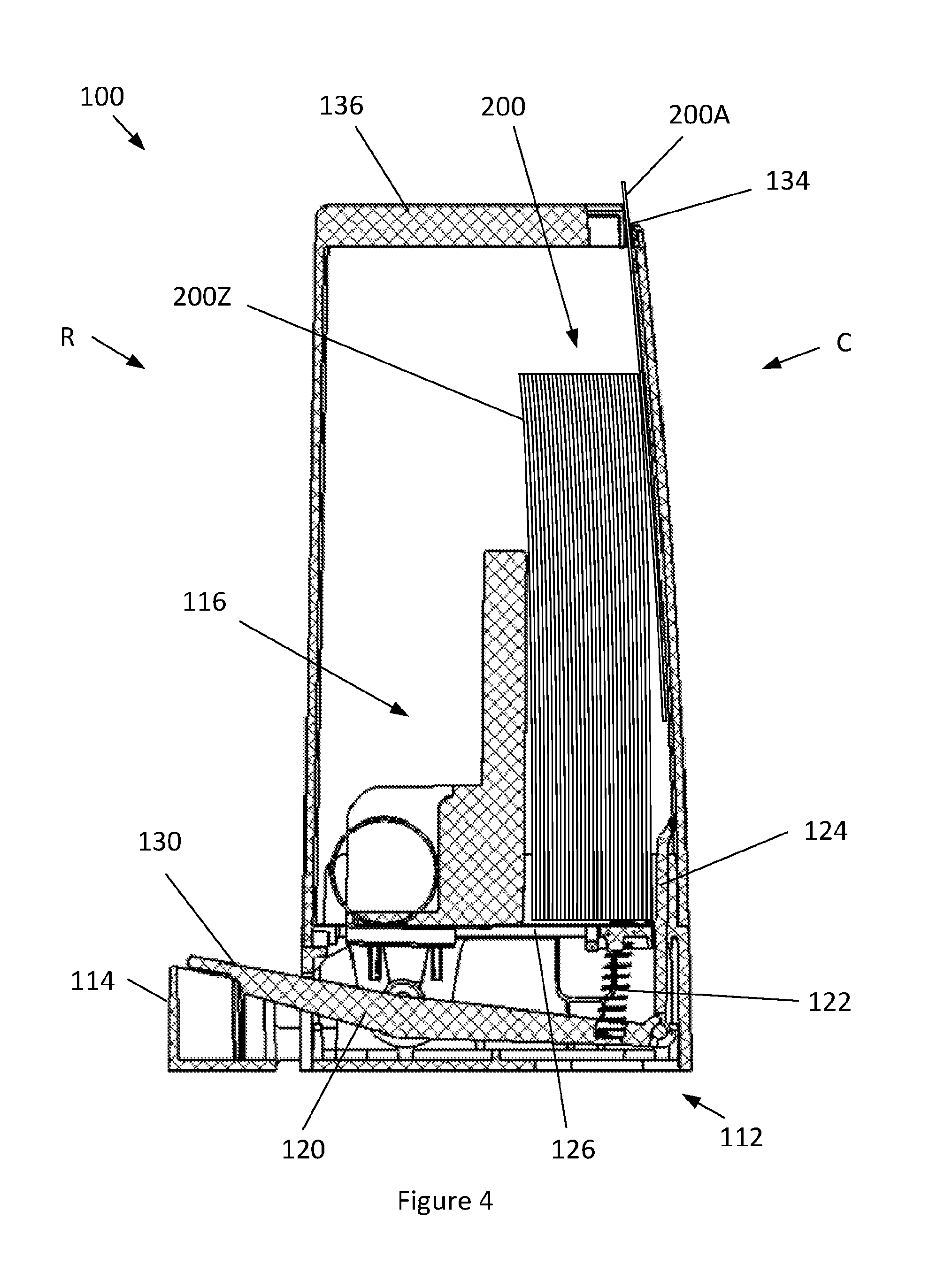
[0058]The ticket dispenser 100 comprises a ticket rack assembly 102, a ticket housing 104, and a counter base 106.

[0059]The ticket rack assembly 102 comprises a ticket rack 108, a ticket biasing mechanism 110, a ticket dispensing mechanism 112, and a lock 114. The ticket biasing mechanism 110 comprises a pusher unit 116 and a torsion spring 118 for driving the pusher unit. The ticket dispensing mechanism 112 comprises a dispensing lever 120, a pivoting peg 120A, a compression spring 122 and a ticket ejector 124.

[0060]The ticket rack 108 has a support platform ...


PUM

PropertyMeasurementUnit
thicknessaaaaaaaaaa
thicknessaaaaaaaaaa
widthaaaaaaaaaa

Abstract

A ticket dispenser for dispensing a ticket from a pack of tickets having first and last tickets at opposite ends of the pack and each ticket having opposed first and second edges, the ticket dispenser comprising: a ticket rack assembly having a rack with a support platform for receiving the pack of tickets with first edges against the support platform, and a ticket pack biasing mechanism configured to bias against a face of the last ticket of the C pack and to urge the last ticket towards the first ticket; a ticket housing for preventing unauthorised external access to the pack of tickets, the ticket housing comprising a ticket dispensing slot; and a ticket dispensing mechanism configured to dispense the first ticket from the pack of tickets, the ticket dispensing mechanism comprising a dispensing control member connected to a ticket ejector, the ticket ejector having a ticket edge engagement feature configured to engage with a first edge of the first ticket, the ticket ejector being operable by movement of the dispensing control member to slide the first ticket from the pack and away from the platform and to dispense the second edge of the first ticket through the ticket dispensing slot.

Description

FIELD OF INVENTION[0001]The present invention relates to a ticket dispenser for dispensing a ticket from a pack of separate, flexible tickets that are mounted in the dispenser, and more particularly, but not exclusively, for dispensing scratch cards.BACKGROUND[0002]GB205164 describes a known ticket dispenser for dispensing thick railway tickets, which receives a stack of separate tickets, laid on and parallel to the surface of a flat horizontal platform, and is configured to dispense the lowermost ticket (i.e. the ticket adjacent the platform) from the stack. The dispenser is designed for a customer to operate, to self-issue a ticket. The ticket dispenser is operated by pushing a pivoting panel into the base of the dispenser, which operates a complex mechanical linkage to drive a ticket ejector. The ticket ejector is slidably connected to the platform, and engages the back edge of a ticket to dispense the front edge of the lowermost ticket out through a dispensing aperture, towards ...

Claims


Application Information

Patent Timeline
Patent Type & Authority Applications(United States)
IPC IPC(8): G07B3/04B65H5/36G07B5/08B65H5/16
CPCG07B3/04G07B5/08B65H5/36B65H5/16B65H1/022B65H3/24B65H3/56B65H2301/51214B65H2402/443B65H2402/46B65H2403/53B65H2404/623B65H2701/1936A47F1/12B65D83/12G07B7/00
Inventor BARRETT, JOHNMATTHEWS, STEVESHARDLOW, PAUL
Owner FASTRAK RETAIL UK
Why Eureka
Try Eureka