Electroacoustic transducer
- Summary
- Abstract
- Description
- Claims
- Application Information
AI Technical Summary
Benefits of technology
Problems solved by technology
Method used
Image
Examples
first embodiment
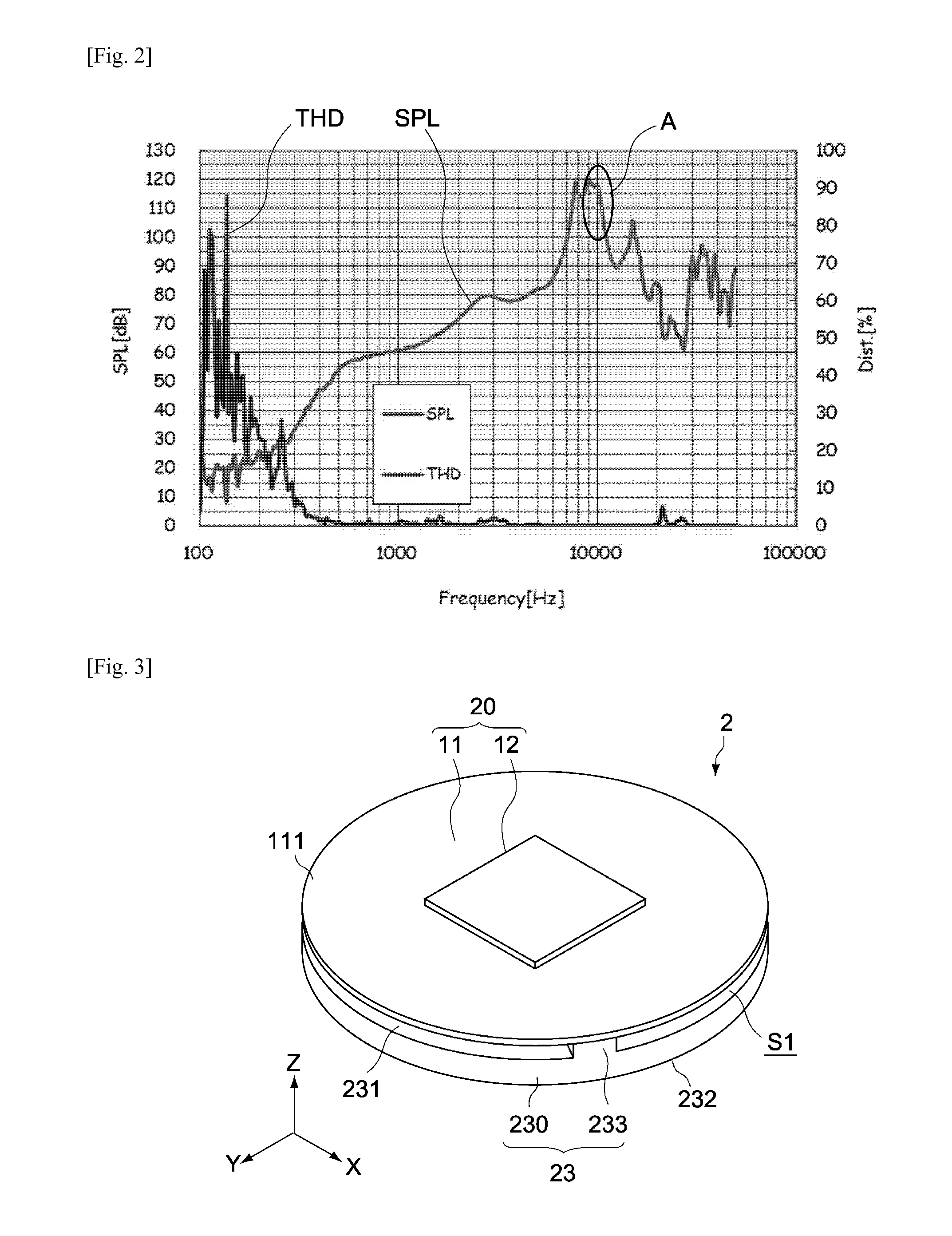
[0069]FIG. 3 is a general perspective view of a speaker unit pertaining to the first embodiment of the present invention, while FIG. 4 is an exploded perspective view of the same.
[0070]The speaker unit 2 in this embodiment has a piezoelectric speaker 20 and support member 23.
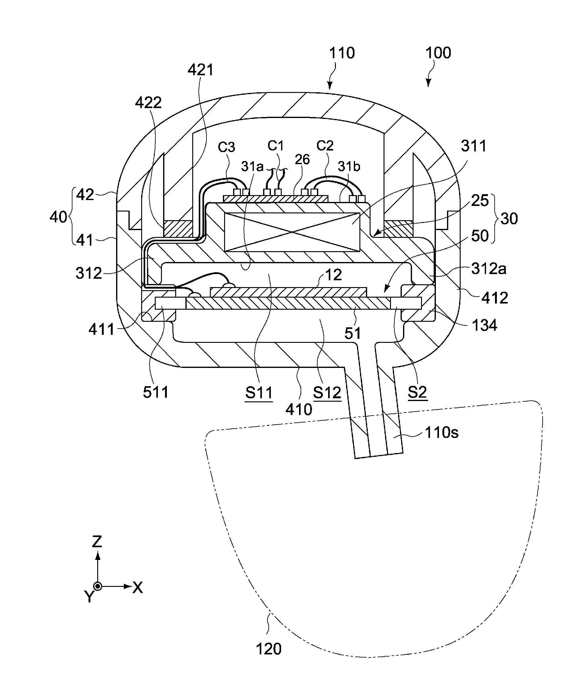
[0071]The speaker unit 2 is housed inside a housing not illustrated here, to constitute an electroacoustic transducer for an earphone, headphone, etc.
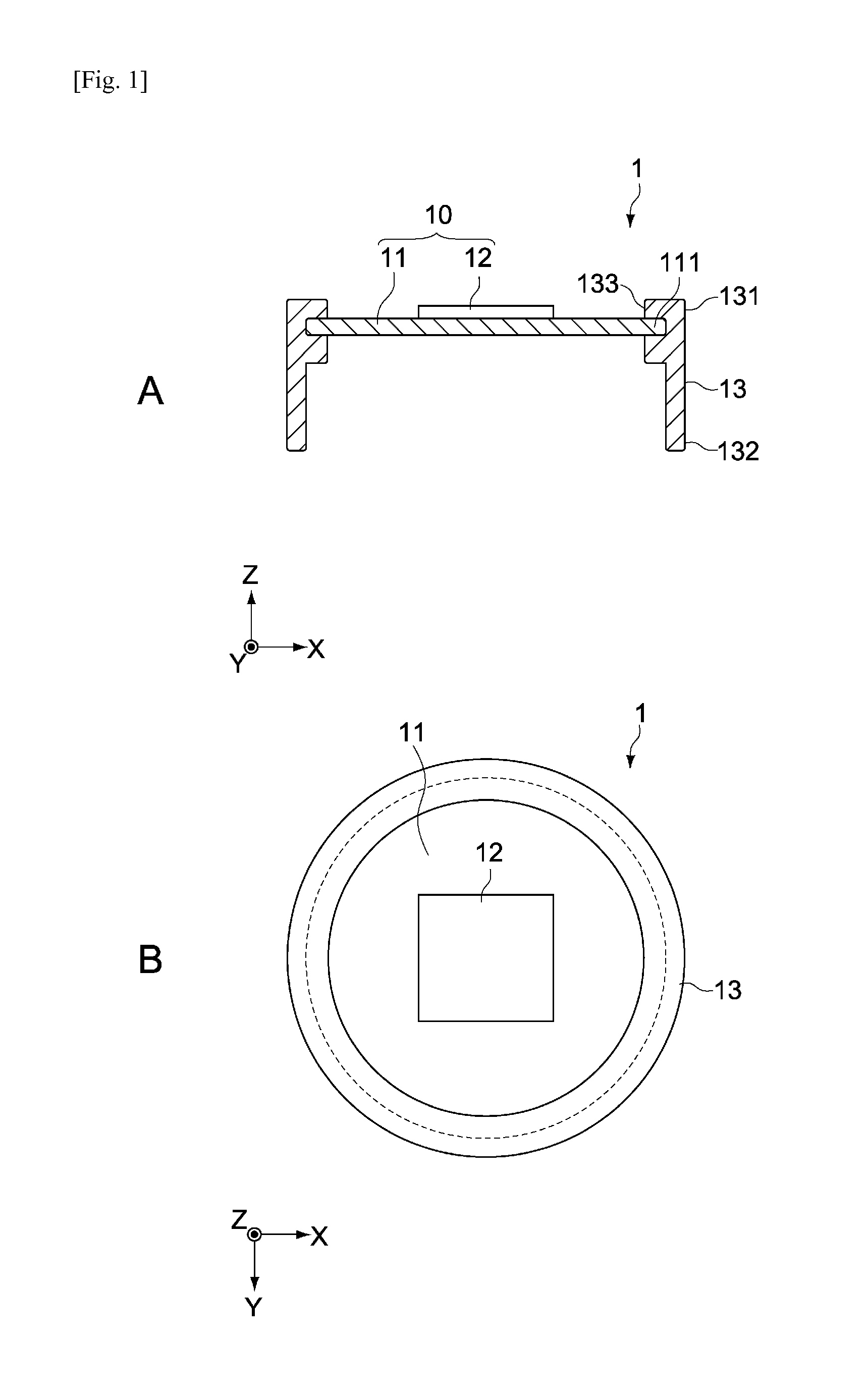
[0072]The piezoelectric speaker 20 has a vibration plate 11 and piezoelectric element 12. The vibration plate 11 and piezoelectric element 12 are constitutionally identical to the vibration plate 11 and piezoelectric element 12 of the electroacoustic transducer 1 pertaining to the aforementioned reference example and therefore are not explained here.
[0073]On the other hand, the support member 23 supports the vibration plate 11 in multiple areas of its periphery 111. The support member 23 may be constituted by a part of the housing or by a member independent of the ...
second embodiment
[0087]FIG. 7 is a schematic lateral section view showing the constitution of a speaker unit 3 pertaining to the second embodiment of the present invention. Constitutions different from those of the first embodiment are primarily explained below, and the same constitutions as in the first embodiment are not explained or explained briefly using the same symbols.
[0088]The speaker unit 3 in this embodiment has a piezoelectric speaker 20 and support member 33. The speaker unit 3 is housed inside a housing not illustrated here, to constitute an electroacoustic transducer for an earphone, headphone, etc.
[0089]In this embodiment, the support member 33 elastically supports the periphery 111 of the vibration plate 11 all around. The support member 33 may be constituted by a part of the housing or by a member independent of the housing.
[0090]The support member 33 has an annular body 330, and a ring-shaped convex 333 that supports the periphery 111 of the vibration plate 11. The support member ...
third embodiment
[0100]A and B in FIG. 10 are a schematic lateral section view and plan view, respectively, showing the constitution of a speaker unit 4 pertaining to the third embodiment of the present invention. Constitutions different from those of the first embodiment are primarily explained below, and the same constitutions as in the first embodiment are not explained or explained briefly using the same symbols.
[0101]The speaker unit 4 in this embodiment has a piezoelectric speaker 20 and support member 43. The speaker unit 4 is housed inside a housing not illustrated here, to constitute an electroacoustic transducer for an earphone, headphone, etc.
[0102]In this embodiment, the support member 43 supports the vibration plate 11 in multiple areas of its periphery 111. The support member 43 may be constituted by a part of the housing or by a member independent of the housing.
[0103]The support member 43 has an annular body 430, and multiple projections 433 to support the periphery 111 of the vibrat...
PUM
 Abstract
Description
Claims
Application Information
 - R&D
- Intellectual Property
- Life Sciences
- Materials
- Tech Scout
- Unparalleled Data Quality
- Higher Quality Content
- 60% Fewer Hallucinations
Browse by: Latest US Patents, China's latest patents, Technical Efficacy Thesaurus, Application Domain, Technology Topic, Popular Technical Reports.
© 2025 PatSnap. All rights reserved.Legal|Privacy policy|Modern Slavery Act Transparency Statement|Sitemap|About US| Contact US: help@patsnap.com


