Communication control method, base station, and user terminal

Active Publication Date: 2016-06-02
KYOCERA CORP
View PDF11 Cites 8 Cited by
  • Summary
  • Abstract
  • Description
  • Claims
  • Application Information

AI Technical Summary

Benefits of technology

[0008]Therefore, the present invention provides a communication control method with which it is possible to measure a channel state from a user terminal while preventing a radio resource from being oppressed in view of a whole system without a need of defining anew uplink reference signal, a base station therefor, and a user terminal therefor.

Problems solved by technology

However, there is a problem that a user terminal that establishes a connection with abase station transmits an uplink reference signal (SRS) for measuring a channel state between the user terminal and the base station, and thus, when transmitting a new reference signal to measure a channel state between user terminals, it is necessary to add a radio resource for the new reference signal, and therefore, a radio resource is oppressed in view of a whole system.
Further, not only when the channel state between the user terminals is measured, but also when, for example, a channel state between the user terminal and a plurality of base stations (as an example, a macro base station and a small cell base station) is measured, in the present specifications, a common uplink reference signal for measuring a channel state is not defined, and thus, the same problem occurs.

Method used


Image

  • Communication control method, base station, and user terminal
  • Communication control method, base station, and user terminal
  • Communication control method, base station, and user terminal

Examples


first embodiment

Summary of First Embodiment

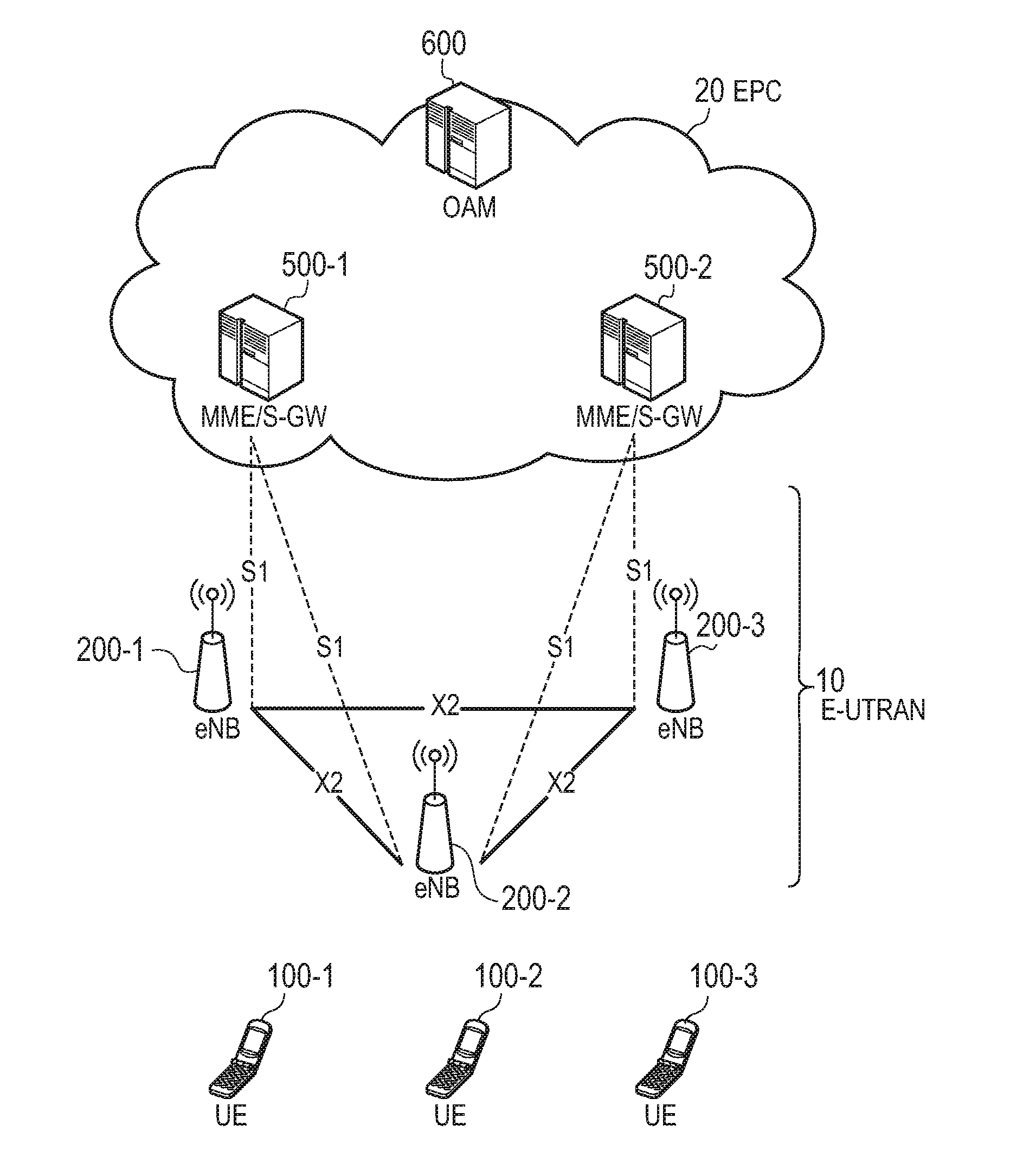
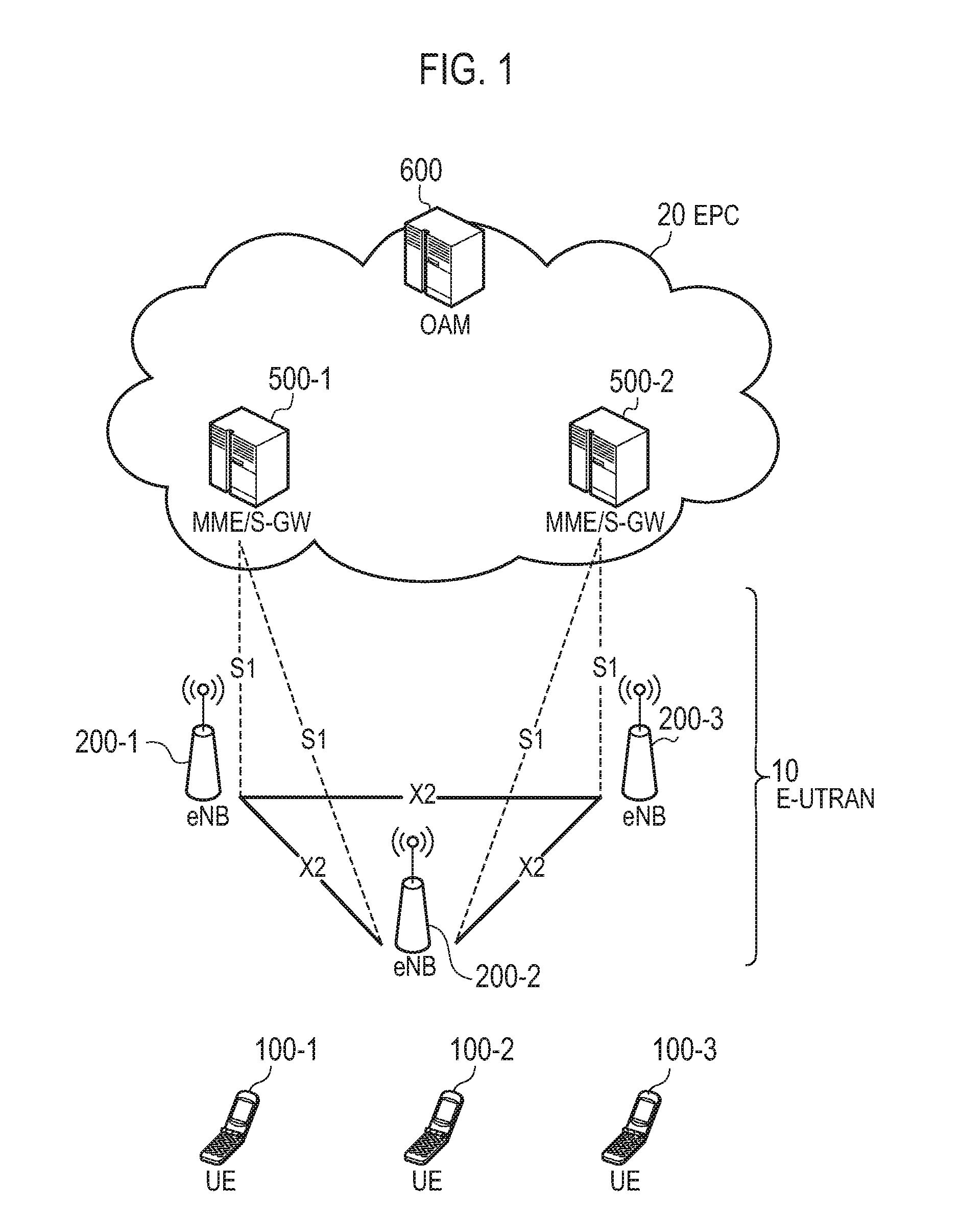
[0131]In the present embodiment, the eNB 200 transmits the reference signal configuration information designating the parameter of the uplink reference signal to each of the respective UEs 100 (the UE 100-2 and the UE 100-3). The UE 100-1 transmits the uplink reference signal to the eNB 200. Each UE 100 receives the uplink reference signal transmitted from the UE 100-1 on the basis of the reference signal configuration information to measure the channel state between each UE 100 and the UE 100-1. As a result, only when the existing uplink reference signal (SRS) is transmitted to the eNB 200 as conventionally, the UE 100-1 is capable of measuring the channel state among each UE 100 without a need of transmitting the reference signal designed to measure the channel state to each UE 100. This eliminates a need for the UE 100-1 to individually transmit the reference signal to each UE 100 to measure the channel state among each UE 100. Further, when the existin...

second embodiment

Summary of Second Embodiment

[0195]In the present embodiment, each communication device (the UE 100-2, the HeNB 250, the PeNB 300, and the AP 400) notifies the MeNB 200 that selects the connection target of the UE 100-1 (and the UE 100-2) of the channel state information, and the MeNB 200 selects the connection target of the UE 100-1 on the basis of the notified channel state information and the channel state measured by the eNB 200. As a result, the connection target having a good communication state is selected on the basis of the channel state with each communication device, and thus, the UE 100-1 becomes capable of performing a good communication.

[0196]Further, in the present embodiment, each communication device (the UE 100-2, the HeNB 250, the PeNB 300, and the AP 400) transmits, together with the Channel report, the communication information on communication of each communication device, and the MeNB 200 selects the connection target of the UE 100-1 on the basis of the channel...


PUM


Abstract

A communication control method according to the present invention comprises: notifying, by the base station, the at least one or more communication devices of reference signal configuration information designating a parameter of the uplink reference signal; transmitting, by the user terminal, the uplink reference signal to the base station; and receiving, on the basis of the reference signal configuration information, by the at least one or more communication devices, the uplink reference signal transmitted from the user terminal; and measuring, on the basis of the received uplink reference signal, by the at least one or more communication devices, a channel state between the at least one or more communication devices and the user terminal.

Description

TECHNICAL FIELD[0001]The present invention relates to a communication control method, a base station, and a user terminal, used in a mobile communication system.BACKGROUND ART[0002]In 3GPP (3rd Generation Partnership Project) which is a project aiming to standardize a mobile communication system, the introduction of device-to-device (D2D) communication is discussed as a new function after Release 12 (see Non Patent Literature 1).[0003]In the D2D communication, a plurality of neighboring user terminals perform direct communication without passing through a core network. That is, a data path of the D2D communication does not pass through the core network. On the other hand, a data path of normal communication (cellular communication) of a mobile communication system passes through the core network.CITATION LISTNon Patent Literature[0004][NPL 1]3GPP Technical Report “TR 22.803 V12.1.0” March 2013SUMMARY OF INVENTION[0005]In the present specifications, there is no mechanism in which a c...

Claims


Application Information

Patent Timeline
Patent Type & Authority Applications(United States)
IPC IPC(8): H04W72/12H04W72/04H04W76/02H04L5/00
CPCH04W72/1231H04W76/023H04W72/0413H04L5/0048H04W92/18H04L5/0051H04L5/0091H04W76/14H04W16/28H04W72/542H04W72/21
Inventor SAIWAI, TAKAHIROFUJISHIRO, MASATOINAKOSHI, ATSUHISAMURITA, KUGO
Owner KYOCERA CORP
Why Eureka
Try Eureka