
Robotic device for dental surgery

a robotic device and dental surgery technology, applied in dental surgery, manufacturing tools, impression caps, etc., can solve the problems of increasing discomfort of patients having to have additional procedures, affecting the healing process of gingival cavities, and requiring expensive intraoral scanning equipmen

Active Publication Date: 2016-06-09
BIOMET 3I LLC
View PDF11 Cites 20 Cited by
  • Summary
  • Abstract
  • Description
  • Claims
  • Application Information

AI Technical Summary

Benefits of technology

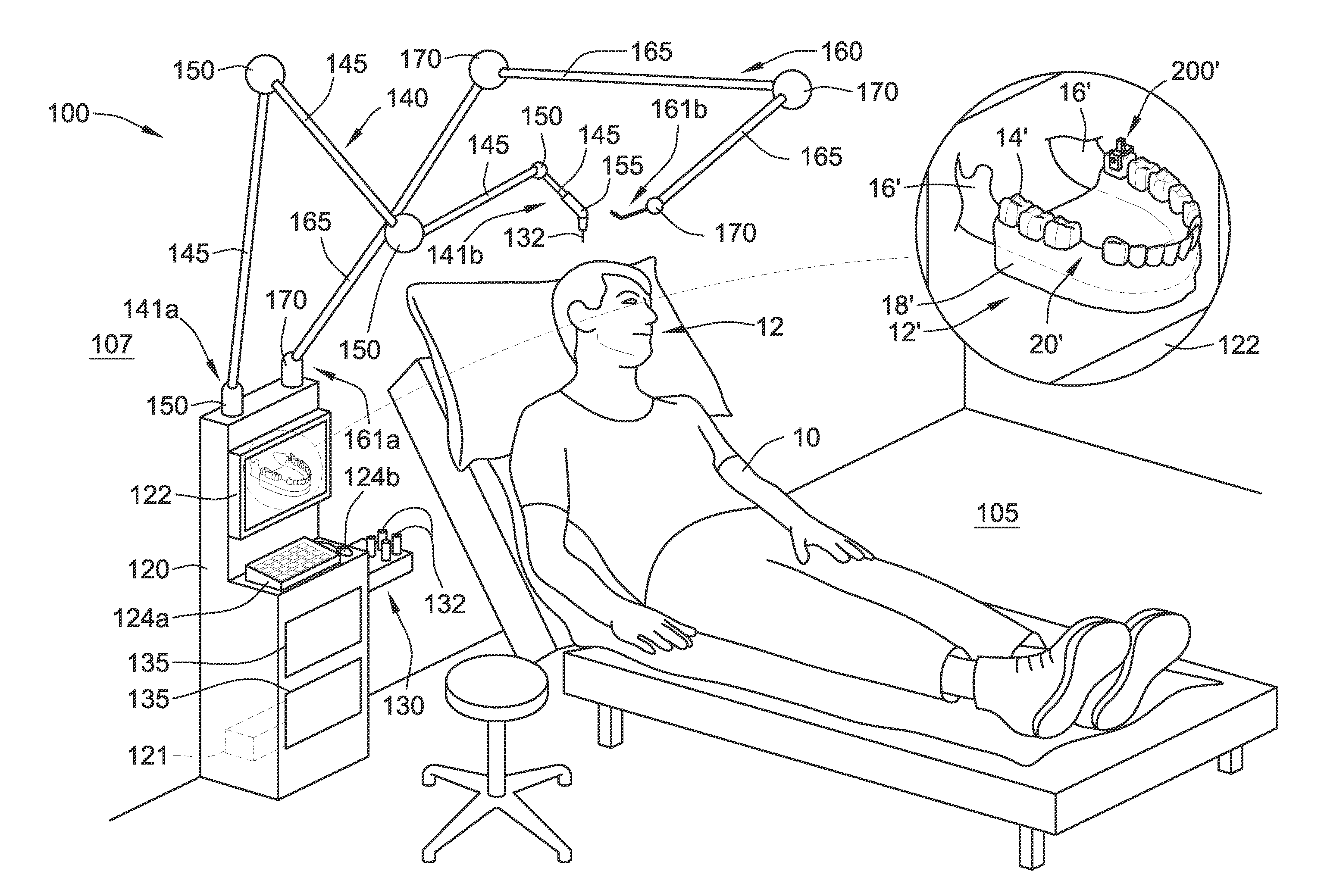
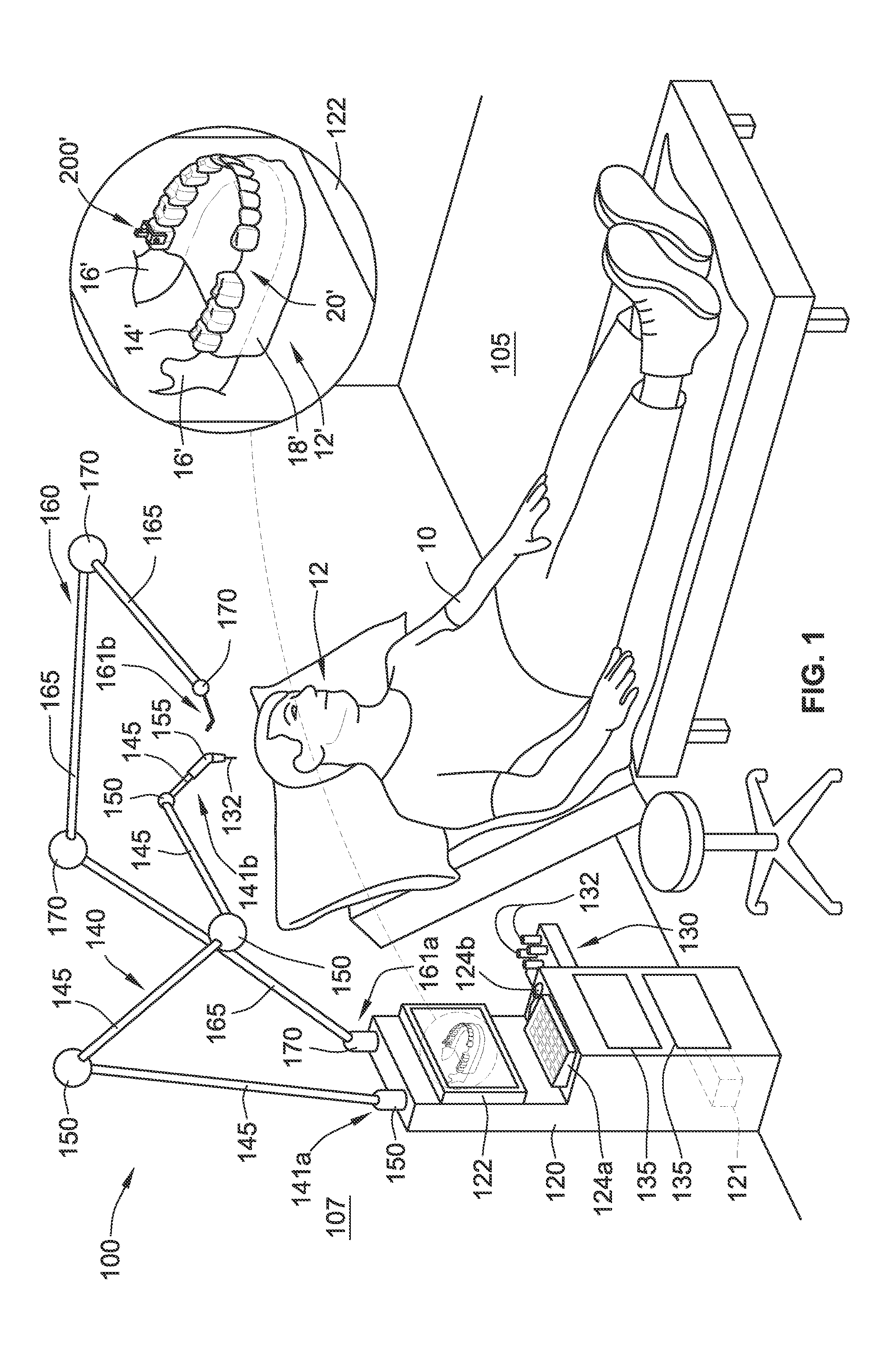
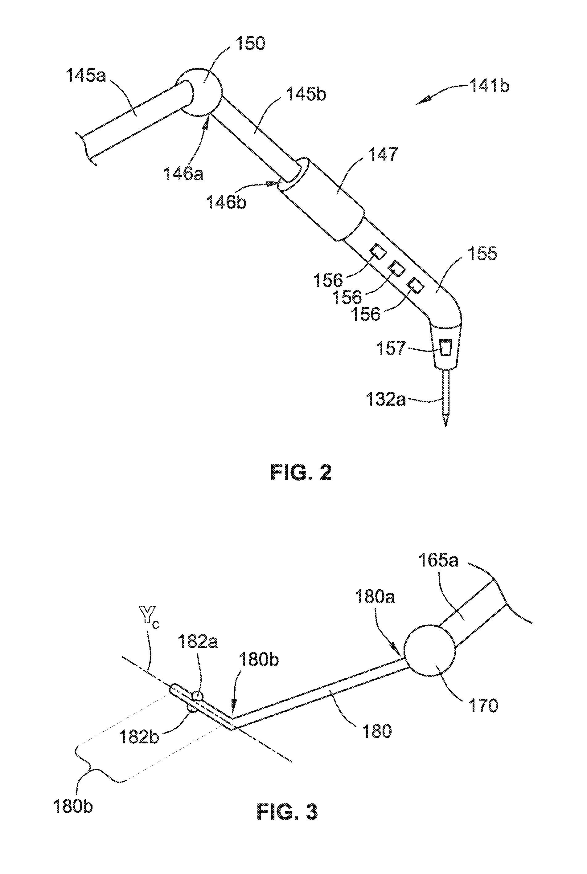
The patent describes a robotic system for use during dental procedures, specifically the installation of dental implants. The system includes a base, a grounding arm, and a working arm. The grounding arm is attached to the patient's mouth to establish a reference point for the system. The working arm has degrees of freedom relative to the base and is designed to hold a dental tool for shaving bone or installing the dental implant. The system also includes sensors that monitor the position of the grounding arm and the working arm, allowing for precise positioning of the dental tool. The system can create a virtual model of the patient's mouth based on pre-operative data and use it to guide the dental procedure. The technical effects of the system include improved accuracy and efficiency in dental procedures and reduced risk of complications.

Problems solved by technology

The replacing of the healing abutment with the scanning abutment, even for a short period of time, has disadvantages, such as, added discomfort to the patient having to have additional procedures performed, disruption to the gingival healing process, etc.
While these systems do not require the removal of the healing abutment to create the virtual three-dimensional model, they still do require the intraoral scanning step, which requires expensive intraoral scanning equipment.

Method used


Image

  • Robotic device for dental surgery
  • Robotic device for dental surgery
  • Robotic device for dental surgery

Examples


implementation 12

[0115] The robotic system of implementation 8, wherein one or more processors of the robotic system are configured to control movement of the working arm to automatically install the dental implant in the mouth of the patient according to a pre-planned installation procedure, wherein the working arm is coupled to a dental-implant-driving tool during the automatic installation.

[0116]Implementation 13. The robotic system of implementation 12, wherein at least one of the one or more processors is configured to control movement of the working arm to automatically remove a portion of a jaw bone of the patient, thereby forming a socket for receiving the dental implant, according to the pre-planned installation procedure, wherein the working arm is coupled to a drill-bit tool during the removal.

[0117]Implementation 14. The robotic system of implementation 8, wherein a tip of the grounding arm has at least six degrees of freedom relative to the base and wherein a tip of the one or more tool...


PUM


Abstract

A robotic system includes a base, a grounding arm, a working arm, and one or more sensors. The grounding arm extends from the base and is configured to be coupled to a fixed structure within the mouth of the patient for establishing an origin for the robotic system. The working arm extends from the base and is configured to be coupled with one or more tools for use during an installation of a dental implant in the mouth. The one or more sensors are for monitoring positions of the grounding arm and / or the working arm and to generate positional data that is used to create a post-operative virtual three-dimensional model of at least a portion of the mouth of the patient.

Description

CROSS-REFERENCE TO RELATED APPLICATIONS[0001]This application claims the benefit of U.S. Provisional Application No. 62 / 170,038, filed Jun. 2, 2015, and U.S. Provisional Application No. 62 / 089,580, filed Dec. 9, 2014, each of which is hereby incorporated by reference herein in its entirety.FIELD OF THE INVENTION[0002]The present disclosure relates generally to robotic systems and methods of using the same. More particularly, the present disclosure relates to using a robotic system to (i) automatically perform a variety of dental procedures and / or (ii) monitor a manually performed dental procedure, thereby generating positional data of the robotic system that is usable in creating a modified three-dimensional model for use in developing a final and / or temporary dental prosthesis (e.g., crown, abutment, etc.).BACKGROUND OF THE INVENTION[0003]The dental restoration of a partially or wholly edentulous patient with artificial dentition typically begins with an incision being made through...

Claims


Application Information

Patent Timeline
IPC IPC(8): A61C8/00B25J9/16A61C3/02A61C3/12A61C9/00A61C1/08
CPCA61C8/0089A61C9/004A61C1/084A61C3/02A61C3/12Y10S901/09A61B19/2203B25J9/1682B25J9/163Y10S901/41A61B19/5244A61C1/00A61C1/12A61B34/70A61B34/30A61B2034/101A61B2034/102A61B2034/2059A61B34/20A61C9/0046A61B90/03A61B2034/105
Inventor SUTTIN, ZACHARY B.PORTER, STEPHAN S.
Owner BIOMET 3I LLC
Learn More