Thread Manufacture for Filament Wound Mandrel

a technology thread, which is applied in the direction of screw threads, other domestic articles, drilling pipes, etc., can solve the problems of reducing and reducing the consolidation of filament wound mandrels to allow, so as to reduce or eliminate the typical machining time and increase the strength of threads

Inactive Publication Date: 2016-06-16
WEATHERFORD TECH HLDG LLC
View PDF0 Cites 5 Cited by
  • Summary
  • Abstract
  • Description
  • Claims
  • Application Information

AI Technical Summary

Benefits of technology

[0025]For each of the disclosed techniques, the thread is molded and not machined (except in finishing steps). These molding tech...

Problems solved by technology

Filament wound mandrels are too consolidated to allow for reliable molding of the threads post-wrapping.
The consolidated material does not move when the overmold is applied, and fiber breakage can occur in the material.
However, such post-cure machining breaks the continuous fiber reinforcement 22 of the filament winding.
In the end, this reduces the mechanical properties of the thread 24—particularly limiting the mechanical properties at elevated temperatures.
Unfortunately, as already noted, machining breaks the reinforcement and thereby reduces the mechanical advantage of continuous reinforcement.
However, this procedure requires the manufactured part to have a significant draft angle with t...

Method used


Image

  • Thread Manufacture for Filament Wound Mandrel
  • Thread Manufacture for Filament Wound Mandrel
  • Thread Manufacture for Filament Wound Mandrel

Examples


Embodiment Construction

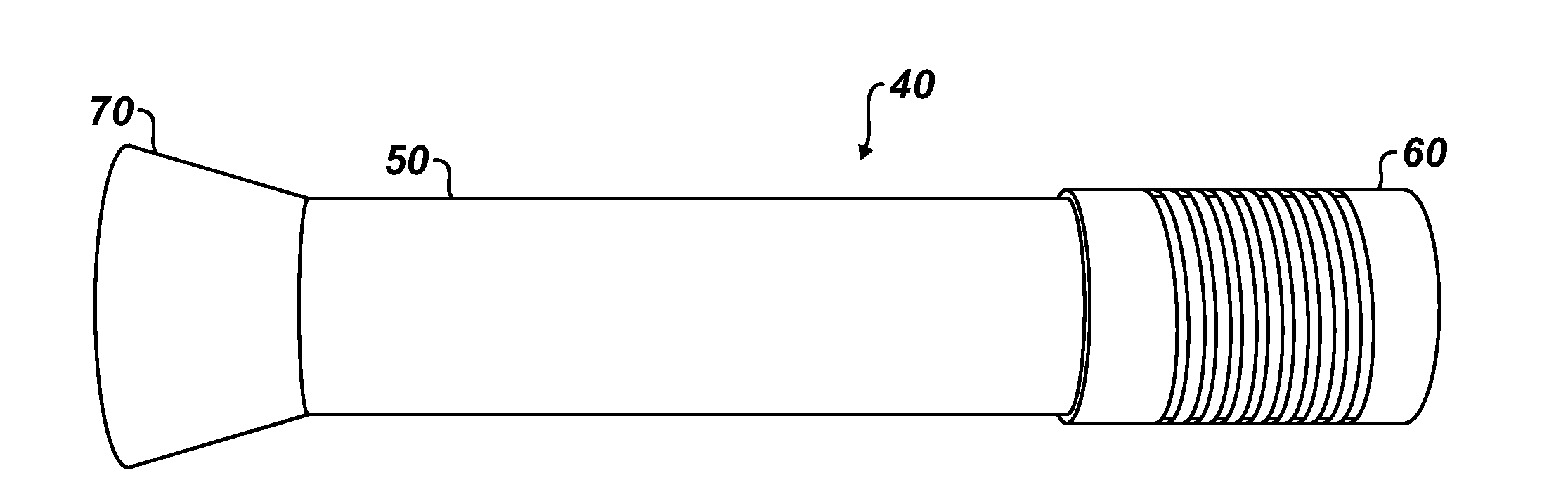
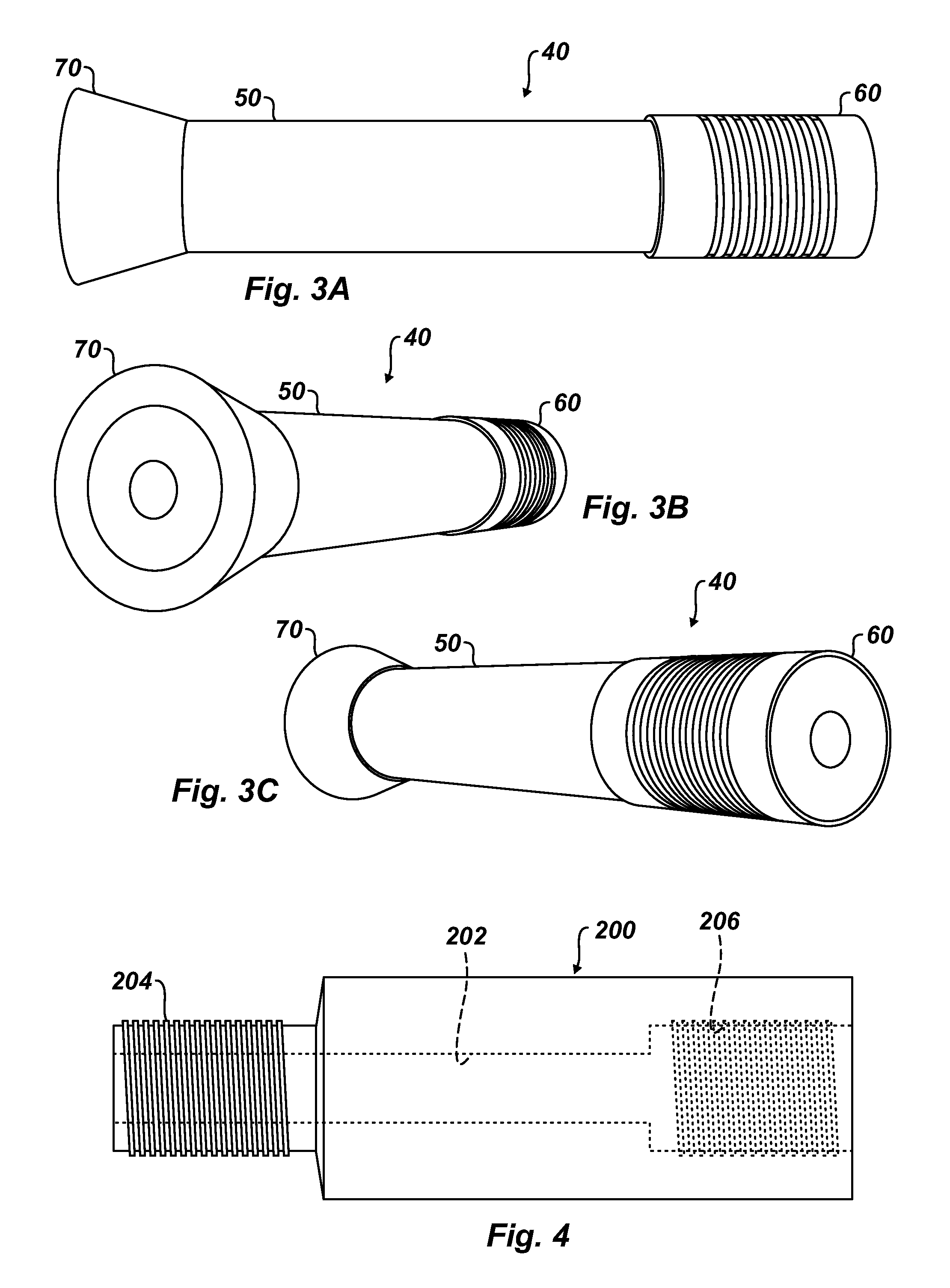
[0040]FIGS. 3A-3C illustrate views of core components 40 for forming a composite mandrel having internal and external threads according to the present disclosure. As an example, FIG. 4 illustrates a mandrel 200 composed of a composite material, such as wound filament and resin matrix, which has been formed using the core components 40 of FIGS. 3A-3C. On the mandrel 200 in FIG. 4, male thread 204 and female thread 206 are integrated into the composite mandrel 200 during fabrication and are not formed by machining.

[0041]As shown in FIGS. 3A-3C, the core components 40 include a tooling core or bar 50 about which filament of a composite mandrel is wound to form a cylindrical mandrel. In the present configuration, the tooling core 50 is a tooling piece used to create the inner bore of a composite tube for the cylindrical mandrel or other disclosed component. In this case, the tooling core 50 has an OD generally equal to the desired ID of the formed mandrel. The tooling core 50 is typical...


PUM

PropertyMeasurementUnit
Thicknessaaaaaaaaaa
Shapeaaaaaaaaaa
Widthaaaaaaaaaa

Abstract

A continuously reinforced composite mandrel is molded by creating an excess of material through a tapered cone and pressing a male thread profile on the exterior of the mandrel at the excess. To form the female thread, an integral component can be used as a separate component in the mandrel to mold the shape of the threads. The integral component is a sufficiently thin shell to transfer mechanical loads to the composite mandrel (i.e. the integral component does not carry significant mechanical loads). Alternatively, to form female threads, a coil is wrapped with the composite material when the mandrel is formed, and the coil is compressed or twisted to an expanded width to form the female threads inside the mandrel. When the coil is relieved, it can be removed from the formed threads.

Description

CROSS-REFERENCE TO RELATED APPLICATIONS[0001]This application claims the benefit of U.S. Provisional Appl. 62 / 092,600, filed 16 Dec. 2014, which is incorporated herein by reference.BACKGROUND OF THE DISCLOSURE[0002]Composite mandrels are used in downhole applications for their drillability, strength, and temperature resistance. The most economical method for manufacturing a composite mandrel is by filament winding. When used downhole, the composite mandrel is typically fastened to other components by shear screws, adhesive bonding, or threading.[0003]As an example, FIG. 1 shows a conventional downhole plug P in partial cross-section. The plug P generally includes a mandrel 10, slips 12a-b, expansion cones 14, backup rings 16, and a synthetic sealing member 18. When the plug P is actuated, the sealing member 18 is used to seal an annular area between the plug P and an inner wall of casing within a wellbore. The above elements are similar to the components disclosed in U.S. Pat. No. 6...

Claims


Application Information

Patent Timeline
IPC IPC(8): B29C70/86B29C70/84E21B17/042B29C70/06
CPCB29C70/865B29C70/06B29K2105/101E21B17/042B29L2001/00B29C70/84B29C70/32B29C53/585B29C59/021
Inventor SABO, STOSCH S.STAGE, MATTHEW R.
Owner WEATHERFORD TECH HLDG LLC
Why Eureka
Try Eureka