Carbon fiber composite material forming tool

A technology of composite materials and forming tooling, which is applied in metal processing and other directions, can solve problems such as the discrepancy between the shape of the product and the design, and the large difference in thermal expansion coefficient between the product and the tooling, achieving excellent dimensional stability, improving service life, and reducing production costs.

Active Publication Date: 2015-05-20
HARBIN
View PDF5 Cites 21 Cited by
  • Summary
  • Abstract
  • Description
  • Claims
  • Application Information

AI Technical Summary

Problems solved by technology

[0004] The purpose of the present invention is to solve the problem that the shape of the product does not match the design due to the large difference in thermal expansion coefficient between the product and the tooling when forming a large-scale, complex-shaped carbon fiber composite aircraft component

Method used


Image

  • Carbon fiber composite material forming tool
  • Carbon fiber composite material forming tool
  • Carbon fiber composite material forming tool

Examples


Embodiment Construction

[0015] The present invention will be described in detail below in conjunction with the accompanying drawings.

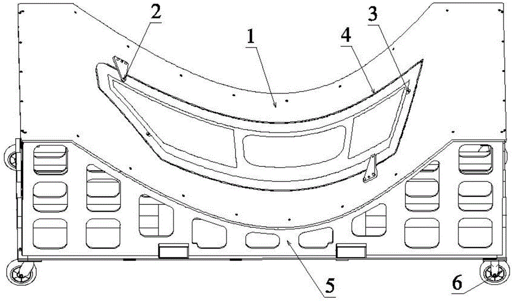
[0016] The invention adopts a thin shell structure, which is mainly composed of two parts: a mold body and a frame. The present invention consists of structure 1 mold body, structure 2 for drilling assembly coordination positioning holes, structure 3 for positioning positioning holes, structure 4 anti-slip belt, structure 5 frame, structure 6 wheels, a total of 6 parts.

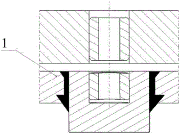
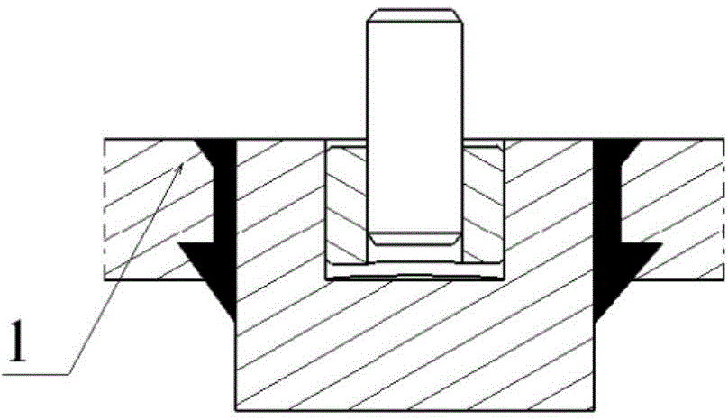
[0017] Structure 1. The material of the mold body is 10mm-14mm Invar steel and other thick steel plates. The surface finish is Ra=1.6μm. The mold body is divided into two parts: the working area and the non-working area. The concave shape is the same as the convex side shape of the product digital model, and the product is placed in the middle of the concave mold working area of ​​the mold body according to the convex side shape during use. Outside the work area of ​​the die body and the die, first...


PUM

PropertyMeasurementUnit
surface smoothnessaaaaaaaaaa

Abstract

The invention belongs to the technology of airplane assembly tools and relates to a carbon fiber composite material forming tool, aiming at solving the problem that a product is inconsistent with the design in shape due to great difference of heat expansion coefficients of the product and a tool when a large-sized carbon fiber composite material airplane member with a complicated surface is formed. The tool provided by the invention is of a thin shell type structure and mainly comprises a die body and a frame. The tool provided by the invention consists of six parts, namely a structure 1, the die body, a structure 2 for drilling assembling and coordinating positioning holes, a structure 3 for preparing the positioning holes, a structure 4, an anti-skid belt, a structure 5, the frame, and a structure 6, wheels. The carbon fiber composite material forming tool provided by the invention can be used for solving the problem that the product is inconsistent with the design in shape due to great difference of heat expansion coefficients of the product and the tool when the large-sized carbon fiber composite material airplane member with the complicated surface is formed. Moreover, as steel tiles are excellent in dimensional stability, the service life of the tool is prolonged and the production cost is lowered.

Description

technical field [0001] The invention belongs to the aircraft assembly tool technology, and relates to a carbon fiber composite material forming tool. Background technique [0002] At present, some foreign professional aviation process equipment manufacturers have mastered the design and manufacturing technology of Invar steel forming tooling. Ability to design similar Invar forming tooling. [0003] In the past, aluminum alloy, ordinary carbon steel or composite materials were mostly used as tooling materials in China. The thermal expansion of aluminum alloy and ordinary carbon steel is quite different from that of carbon fiber composite materials, resulting in inconsistencies between the shape of the product after forming and the theoretical shape, and the rigidity of the aluminum alloy tooling is insufficient. , and the tooling made of composite materials has poor surface accuracy and reusability, so these materials cannot meet the batch production of large-scale, complex...

Claims


Application Information

Patent Timeline
Patent Type & Authority Applications(China)
IPC IPC(8): B29C70/34B29C70/54B29C33/00B26F1/16
CPCB26F1/16B29C33/0033B29C70/342B29C70/44B29C70/54B29C70/545
Inventor 刘建波赵红卫王明凯赵薇薇尹荣颖董克华徐天宇黄兴孙金凤
Owner HARBIN
Why Eureka
Try Eureka