Optical assembly with passive alignment

Active Publication Date: 2016-06-16
TE CONNECTIVITY NEDERLAND
View PDF2 Cites 4 Cited by
  • Summary
  • Abstract
  • Description
  • Claims
  • Application Information

AI Technical Summary

Benefits of technology

[0009]The applicants recognize that, rather than relying on the edges of the OED for alignment, the non-functional area of OED may be etched or layered through standard photolithography techniques to create a very precise mechanical feature (for instance an edge, cylinder, square, triangle, etc.), which can be used for passive alignment. This is done while the OED die is still in wafer form, using processes common in the chip manufacturing industry, which are capable of achieving v

Problems solved by technology

This is not straightforward when placing the OED perpendicular to the substrate.
The edges of the OED die are created in the dicing process (for instance with a dicing saw

Method used


Image

  • Optical assembly with passive alignment
  • Optical assembly with passive alignment
  • Optical assembly with passive alignment

Examples


Embodiment Construction

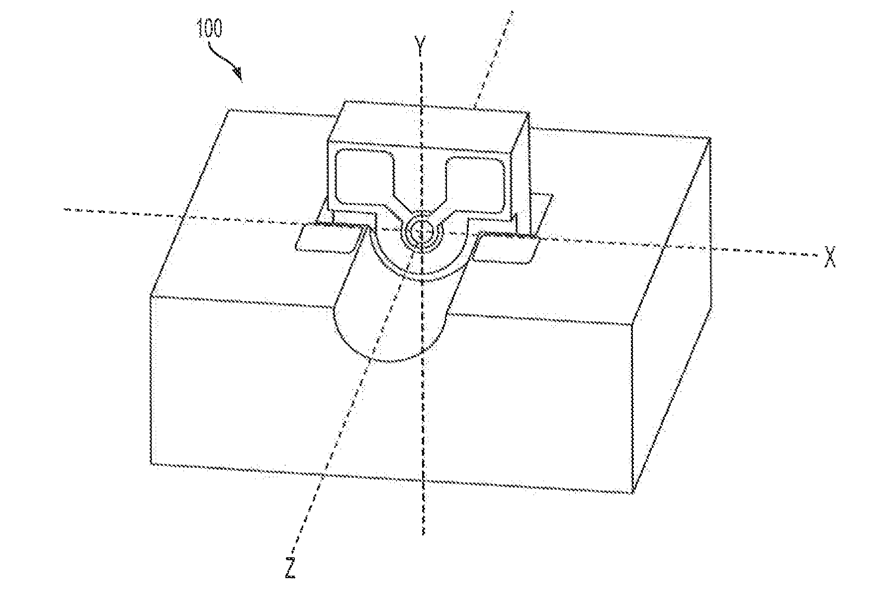
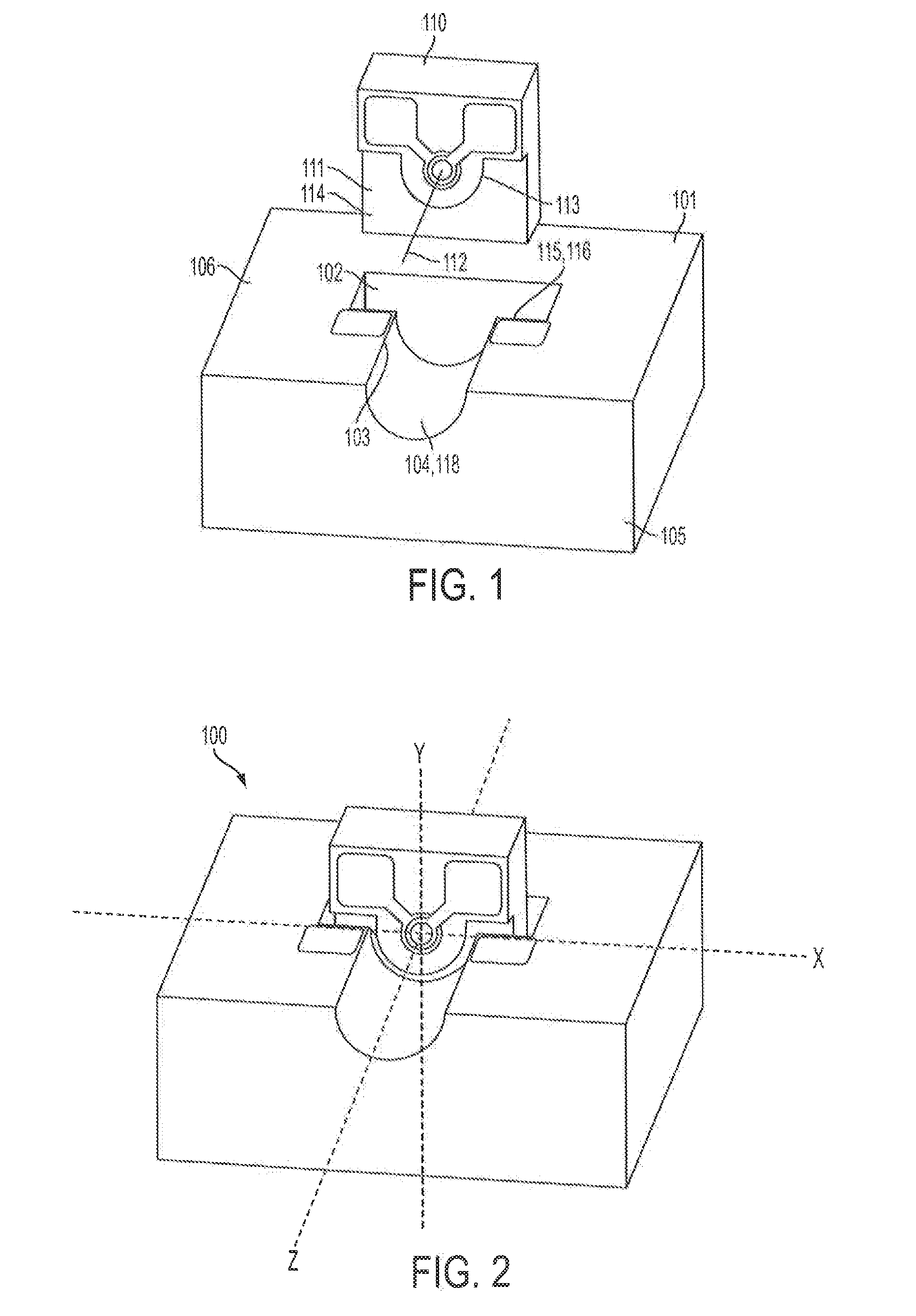
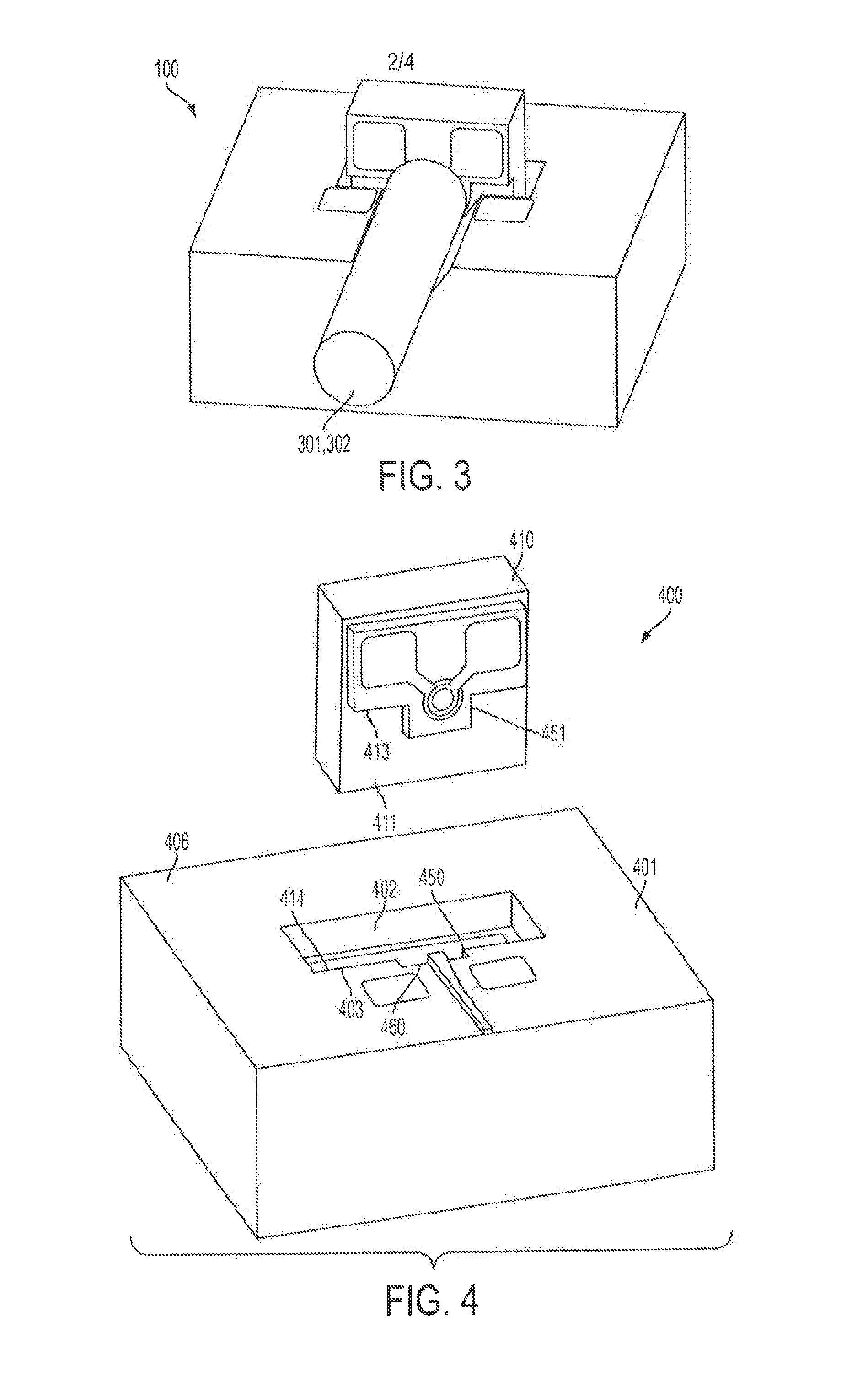
[0017]Referring to FIGS. 1-3, one embodiment of the optical assembly (OA) 100 of the present invention is shown. The OA is described herein in relation to x, y and z axes, although it should be understood that such an orientation is for illustration purposes only and should not be interpreted as limiting the claimed invention. The OA 100 comprises a first substrate 101 having a planar surface 106. The first substrate also comprises a first wall 116, which is perpendicular to the planar surface, and which, in this embodiment, defines a portion of cavity 102 in the planar surface. The first substrate 101 also comprises a first register surface 103 adjacent the first wall, and a foundation 104 for receiving an optical element 301, such as an optical conduit 302 (see FIG. 3), which extends at least partially along the z axis from the first wall 116 to an edge 105 of the substrate. The OA 100 also comprises an opto-electrical device (OED) 110 having a top surface 111 and an optical axis ...


PUM


Abstract

An optical assembly having x, y and z axes and comprising: (a) a first substrate having a planar surface, a first wall adjacent and substantially perpendicular to the planar surface, a first register surface adjacent the first wall, at least one foundation to receive an optical element having a first optical axis at least partially along the z axis; (b) an opto-electrical device (OED) having a top surface, an active area on the top surface having a second optical axis normal to the top surface, and a first alignment element defined on the top surface, the OED mounted to the first wall such that the first alignment element contacts the first register surface to position the OED on the first substrate along at least one of the x or y axes with the second optical axis parallel to the planar surface.

Description

FIELD OF INVENTION[0001]The present invention relates generally to optical subassemblies, and, more particularly to an optical subassembly containing surface emitting opto-electric devices in which the optical axis of the device is parallel with the substrate on which it is mounted.BACKGROUND[0002]Optical systems and devices generally comprise optical assemblies (OAs) of opto-electric devices (OEDs) integrated with optical conduits, such as fibers and waveguides, on a substrate or platform. Critical to the effectiveness of these OAs is the alignment of the OED with this optical conduit. There are generally two alignment approaches for aligning OEDs—active and passive. In passive alignment, registration or alignment features are typically fabricated directly on the components as well as on the platform to which the components are to be mounted. The components are then positioned on the platform using the alignment features and affixed in place. In active alignment, the OEDs are place...

Claims


Application Information

Patent Timeline
IPC IPC(8): G02B6/42
CPCG02B6/4212G02B6/423G02B6/42G02B6/4231G02B6/4243G02B6/4245
Inventor DORRESTEIN, SANDERDUIS, JEROENTUIN, JOEK
Owner TE CONNECTIVITY NEDERLAND
Why Eureka
Try Eureka