Non-contacting monitor for bridges and civil structures

a monitor and bridge technology, applied in the direction of television systems, instruments, image enhancement, etc., can solve the problems of inability to effectively rate the health of labor-intensive current bridge monitoring process, and high cost, and achieve the effect of not being able to use widely, and not being able to effectively rate the bridge on actual current performan

Active Publication Date: 2016-06-16
RDI TECH INC
View PDF6 Cites 56 Cited by
  • Summary
  • Abstract
  • Description
  • Claims
  • Application Information

AI Technical Summary

Benefits of technology

[0009]Objects of the present invention include the following: providing a system for measuring the movement of a structural member in response to a transient load; providing a non-contacting monitor for bridges; providing a system for quantitatively evaluating the response of a structural member to dynamic loads to evaluate the condition of a bridge or other civil structure; providing a system for inspecting a bridge and tracking the condition of the bridge over time; providing a system for comparing the condition of a bridge with that of similar bridges in other locations; providing a system to evaluate the condition of bridges, track their condition over time and in comparison to one another so that improvements and inspection schedules may be prioritized; providing a system for tracking and enforcing compliance with bridge load limits and related vehicle permitting; and, providing a system for non-contacting measurement of deflection of model structures during seismic testing and simulation. These and other objects and advantages of the invention will become apparent from consideration of the following specification, read in conjunction with the drawings.
[0010]According to one aspect of the invention, a system for monitoring bridge loading comprises:
[0011]an optical sensing device fixedly mounted at a selected distance from a bridge and having an unobstructed view of a selected portion of the bridge structure;
[0012]a data processing system to analyze the output of the optical sensing device and calculate a physical displacement of the selected portion of the bridge structure as a function of time;
[0013]a triggering system to trigger an event and generate a time stamp whenever the data processing system detects that the physical displacement exceeds a preset threshold indicating an overload condition;
[0014]at least one digital imaging device fixedly mounted proximate to the bridge and positioned to record images of the vehicles on the bridge at selected times;

Problems solved by technology

The current bridge health monitoring process is labor intensive, expensive, and largely empirical with little data available about real time bridge performance.
None of these tools effectively rates the bridge on actual current performance under load because the only tools available for such measurements are expensive and not feasible for widespread use.
Current infrastructure assessment techniques do not provide a safe environment for inspectors, as they require the use of bucket trucks, rappelling, and other risky means of getting the inspector close to the infrastructure to perform a thorough visual inspection.
The inspector is also subject to danger from vehicular traffic around the inspection site.

Method used


Image

  • Non-contacting monitor for bridges and civil structures
  • Non-contacting monitor for bridges and civil structures
  • Non-contacting monitor for bridges and civil structures

Examples


example

[0152]A short instructional video was posted on the internet, showing operation of a benchtop seismic simulator [Model K50-1206, NaRiKa Corp., Tokyo, Japan]. A small model of a simple seven-floor structure contained a hanging ball in the center of each story to better visualize the motions and resonances that arise in response to various earth movements. Technical details of the video clip are as follows:

[0153]Video ID: y6Z9bsGkMsc

[0154]Dimensions: 640×480*1.75

[0155]Stream type: https

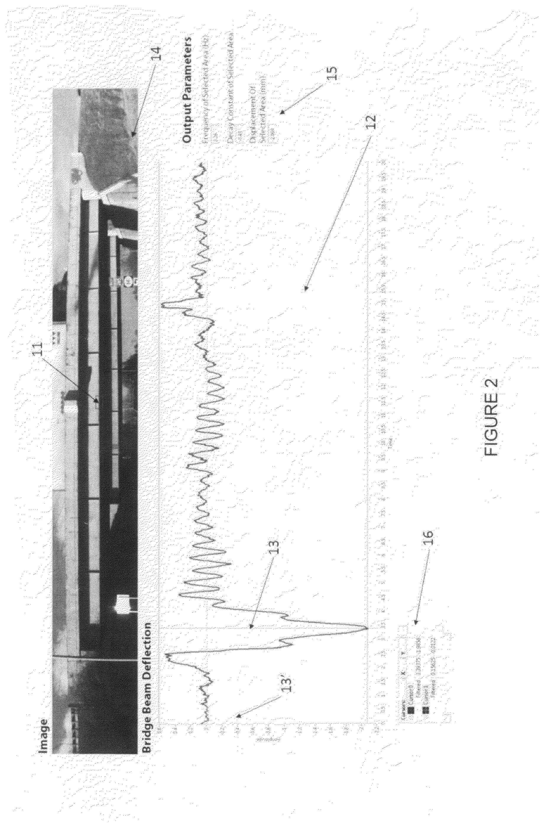
[0156]A segment of this video devoted to the building model, comprising 454 frames representing about 20 seconds of running time, was analyzed using the invention. Working from this one video file, one can select any location and determine the frequency spectrum and the displacement vs. time, and plot these variables using the graphical user interface. Eigen images for particular frequencies may be displayed for visual comparison to the raw video in order to see which parts of the structure have a large...


PUM


Abstract

A method for monitoring the condition of a bridge includes:
    • stably positioning a video camera at a selected location with an unobstructed view of a selected portion of the bridge structure;
    • collecting a video file of the structure over a selected total time interval;
    • using a data processing system to analyze the video and calculate a physical parameter related to movement of the selected portion as a function of time, wherein the data processing system is controlled through a graphical user interface (GUI) having the following features:
      • a display of a single video frame corresponding to a selected time;
      • a movable area selector in the video frame to indicate the selection of an area of the structure for analysis; and,
      • a display of displacement versus time for the selected area over the total time interval.
The processor may perform some tasks, e.g., area selection, autonomously or via predetermined rules.

Description

CROSS-REFERENCE TO RELATED APPLICATIONS[0001]This application claims the benefit of each of the following Provisional patent applications filed by the present inventors: Ser. No. 62 / 090,729, “Optical detection of periodic movement”, filed on Dec. 11, 2014; Ser. No. 62 / 139,127, “Method for determining, comparing, measuring, and displaying phase”, filed on Mar. 27, 2015; Ser. No. 62 / 141,940, “Method and system for analysis of structures and objects from spatio-temporal data”, filed on Apr. 2, 2015; Ser. No. 62 / 139,110, “Adaptive array comparison”, filed on Apr. 14, 2015; Ser. No. 62 / 146,744, “Method of analyzing, displaying, organizing, and responding to vital signals”, filed on Apr. 13, 2015; Ser. No. 62 / 154,011, “Non contact optical baby monitor that senses respiration rate and respiratory waveform”, filed on Apr. 28, 2015; Ser. No. 62 / 161,228, “Multiple region perimeter tracking and monitoring”, filed on May 13, 2015; and Ser. No. 62 / 209,979, “Comparative analysis of time-varying a...

Claims


Application Information

Patent Timeline
Patent Type & Authority Applications(United States)
IPC IPC(8): G06K9/00G06F3/0484G06F17/30H04N7/18
CPCG06K9/00771G06F17/30831G06F3/04842H04N7/183H04N7/18G06F16/7335G06V40/20G06V20/52A61B5/0077A61B5/01A61B5/024A61B5/0816A61B5/165A61B5/4815A61B5/7435G06T7/0016G06T2207/30004G01N29/44G01N2291/028G06T2207/20056G06T2207/20216G06T2207/30164G06F3/04847G06T2200/24G06T2207/10016G06T7/11G06T7/248G06T7/262
Inventor HAY, JEFFREY R.
Owner RDI TECH INC
Why Eureka
Try Eureka