Optical system and image compensating method of optical apparatus
a technology of optical apparatus and optical system, applied in the field of optical system, can solve the problems of difficult to obtain an entire sharp image, the camera cannot detect a clear image under a rather limited working distance range,
- Summary
- Abstract
- Description
- Claims
- Application Information
AI Technical Summary
Benefits of technology
Problems solved by technology
Method used
Image
Examples
first embodiment
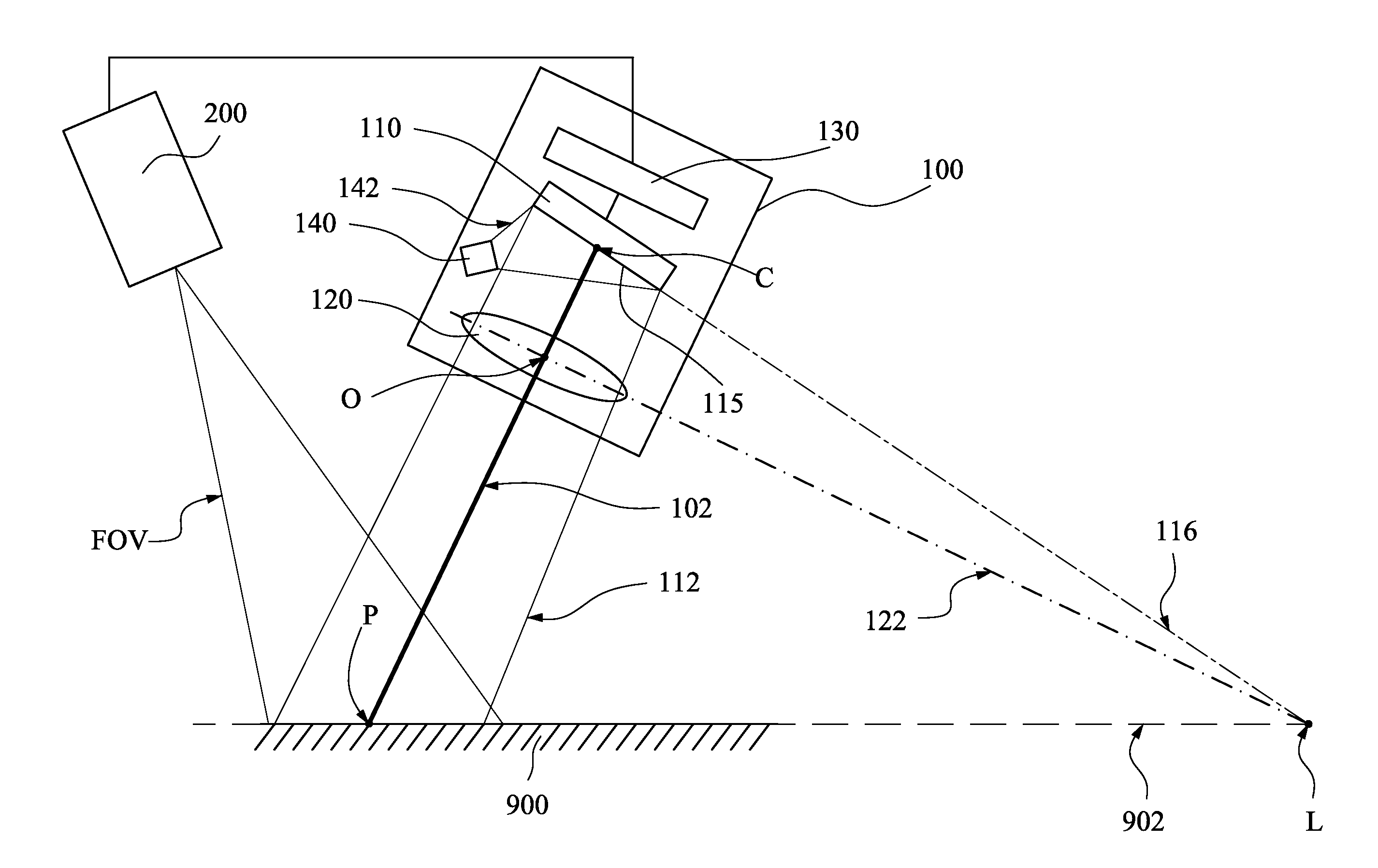
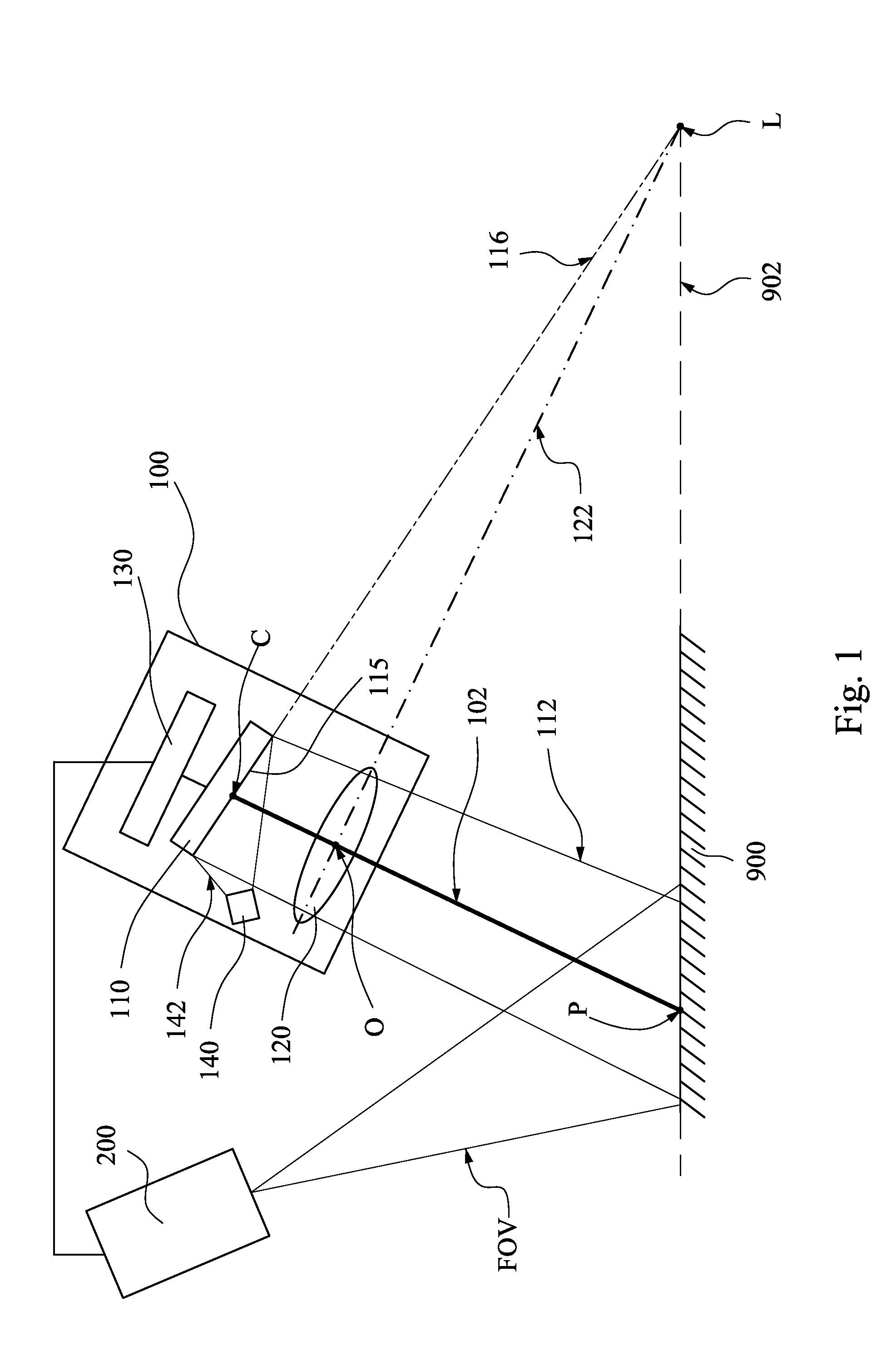
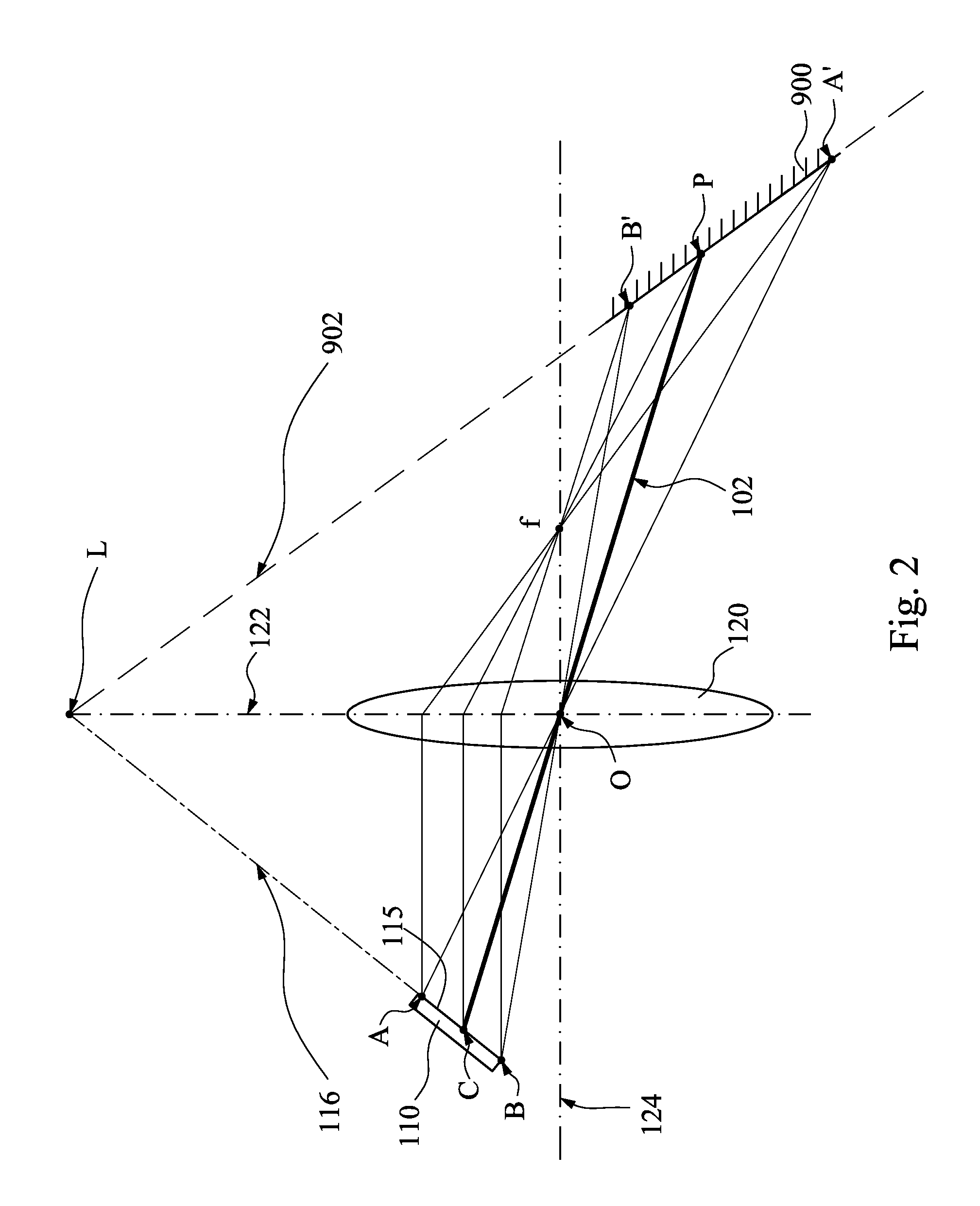
[0038]FIG. 1 is a schematic diagram of an optical system and a plane 900 according to the present invention, and FIG. 2 is a light path schematic diagram of a first image device 110, a lens group 120, and the plane 900 of FIG. 1. The optical system includes at least one optical apparatus 100. For example, the optical system in FIG. 1 includes one optical apparatus 100. The optical apparatus 100 is configured for projecting a first projection image 112 to the plane 900. The optical apparatus 100 includes a first image device 110 and a lens group 120. The first image device 110 has an image surface 115. The image surface 115 has an image center C. The lens group 120 is disposed between the first image device 110 and the plane 900 and has a lens axis surface 122 and an optic center O. The optic center O and the image center C form a connection line 102. The plane 900 has a tangent surface 902 to an intersecting point P of the connection line 102. The lens axis surface 122, the tangent ...
second embodiment
[0050]FIG. 4 is a schematic diagram of an optical system and a plane 900 according to the present invention. In this embodiment, the optical system includes two optical apparatuses 100a and 100b which have the same structures as the optical apparatus 100 of FIG. 1. For clarity, the light sources of the optical apparatuses 100a and 100b are omitted in FIG. 4. The first projection images 112a and 112b of the optical apparatuses 100a and 100b on the plane 900 are separated from each other. This optical system can be applied to a projection system that projects images on a non-flat plane. For example, in FIG. 4, the plane 900 has two portions 910 and 920, and the top surfaces of the two portions 910 and 920 are not parallel. The first projection image 112a of the optical apparatus 100a is projected on the portion 910, and the first projection image 112b of the optical apparatus 100b is projected on the portion 920. For the optical apparatus 100a, the lens axis surface 122a, the tangent ...
third embodiment
[0052]FIG. 5 is a schematic diagram of an optical system and a plane 900 according to the present invention. In this embodiment, the optical system includes two optical apparatuses 100a and 100b which have the same structures as the optical apparatus 100 of FIG. 1. For clarity, the light sources of the optical apparatuses 100a and 100b are omitted in FIG. 5. The first projection images 112a and 112b of the optical apparatuses 100a and 100b are overlapped on the plane 900. For example, the optical apparatuses 100a and 100b can respectively project the first projection images 112a and 112b on the same position of the plane 900 along different directions. For the optical apparatus 100a, the lens axis surface 122a, the tangent surface 902, and the extension surface 116a substantially intersect at the straight line La. For the optical apparatus 100b, the lens axis surface 122b, the tangent surface 902, and the extension surface 116b substantially intersect at the straight line Lb. Theref...
PUM
 Abstract
Description
Claims
Application Information
 - R&D
- Intellectual Property
- Life Sciences
- Materials
- Tech Scout
- Unparalleled Data Quality
- Higher Quality Content
- 60% Fewer Hallucinations
Browse by: Latest US Patents, China's latest patents, Technical Efficacy Thesaurus, Application Domain, Technology Topic, Popular Technical Reports.
© 2025 PatSnap. All rights reserved.Legal|Privacy policy|Modern Slavery Act Transparency Statement|Sitemap|About US| Contact US: help@patsnap.com


