Oil mist separator

a technology of oil mist separator and separator plate, which is applied in the direction of separation process, filtration separation, combustion air/fuel air treatment, etc., can solve the problems of difficult work for bonding or welding the fiber laminate to the desired position of the impinge wall, and the fiber laminate comes off particularly from the impinge wall

Active Publication Date: 2016-06-23
MAHLE JAPAN LTD
View PDF3 Cites 13 Cited by
  • Summary
  • Abstract
  • Description
  • Claims
  • Application Information

AI Technical Summary

Benefits of technology

[0008]Accordingly, an object of the present invention is to elimin

Problems solved by technology

However, in the oil mist separator of this publication, fixing the fiber laminate to the impinge wall is entirely made by only bonding or welding, and thus, it sometimes occurs that the fib

Method used


Image

  • Oil mist separator
  • Oil mist separator
  • Oil mist separator

Examples


first embodiment

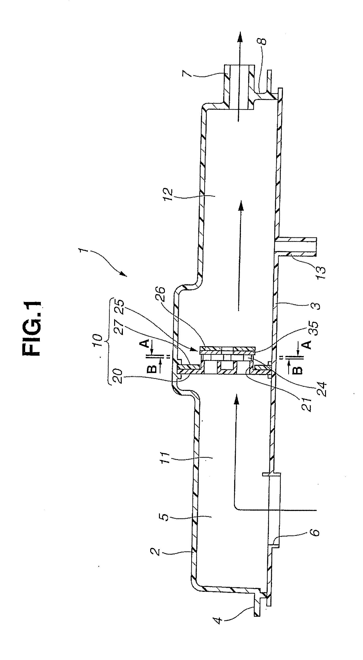
[0028]In the following, the present invention will be described in detail with reference to FIGS. 1 to 9.

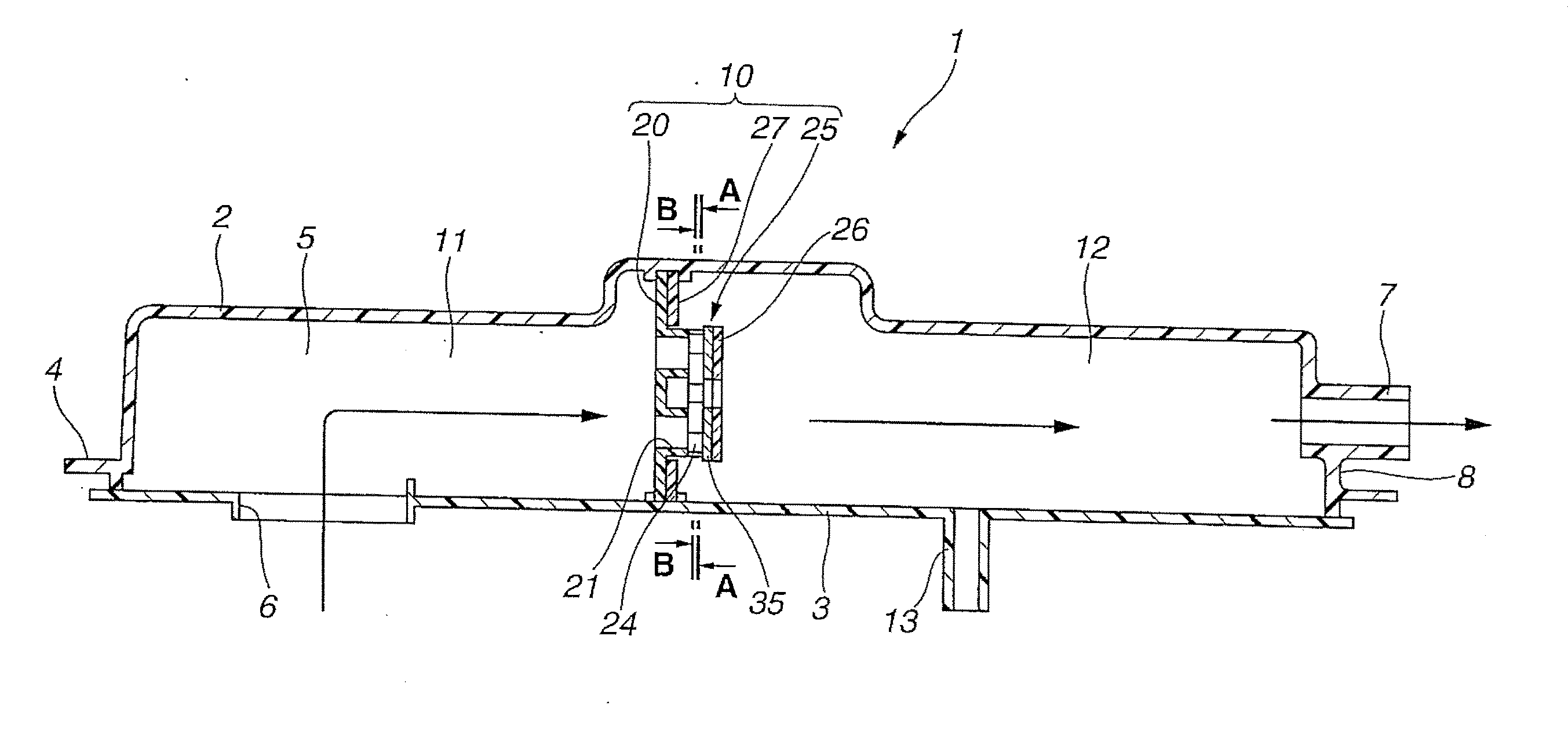
[0029]As is seen from FIG. 1, an of mist separator 1 of the present invention comprises an elongate housing part (or upper cover) 2 that has an opened bottom portion, and a separator cover (or lower cover) 3 that is connected to the opened bottom part of the elongate housing part 2.

[0030]As seen in FIG. 1, the elongate housing part 2 is arranged and constructed to form a part of an upper wall of a cylinder head cover 4 of synthetic resin.

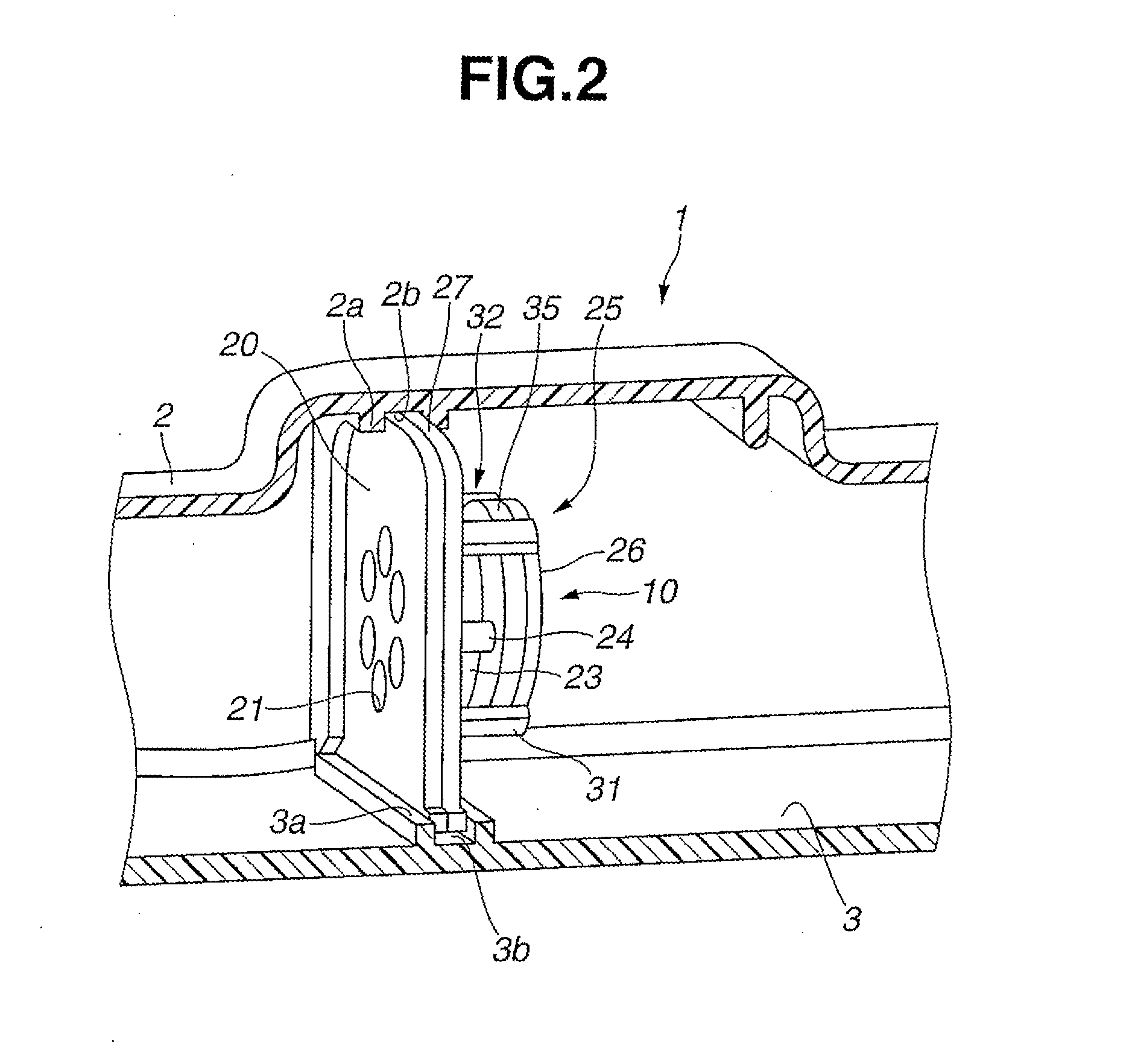
[0031]The separator cover 3 is made of synthetic resin and separately molded from the elongate housing part 2. Bonding and / or welding may be used for connecting the separator cover 3 to the elongate housing part 2. Although, in the illustrated embodiment, the elongate housing part 2 is constructed to integrally form a part of the cylinder head cover 4, the housing part 2 may be provided separately from the cylinder head cover 4.

[0032]In the illus...

second embodiment

[0073]In the following, a separator unit 100 employed in an oil mist separator of the present invention will be described with reference to FIGS. 13 to 16.

[0074]As is seen from these drawings, especially FIG. 13, like in the above-mentioned first embodiment 1, the separator unit 100 employed in the second embodiment comprises a perforated plate 120 that has three small circular openings 121 which are a center one and two side ones that are somewhat higher in position than the center one.

[0075]The perforated plate 120 is rectangular in shape and integrally formed with both a rectangularly swelled portion 123 projected rightward in FIG. 13 from a central portion of the perforated plate 120 and four holding studs 124 projected rightward in FIG. 13 from four corner portions of the perforated plate 120.

[0076]As is seen from the drawings, especially FIG. 13, the separator unit 100 further comprises a rectangular base plate 127 that is formed at its central portion with a rectangular openi...


PUM

PropertyMeasurementUnit
Sizeaaaaaaaaaa
Shapeaaaaaaaaaa

Abstract

A separator unit of an oil mist separator comprises a front unit including a perforated plate and a plurality of holding studs extending rearward from the perforated plate, a rear unit placed behind the perforated plate and including a base plate that is to be intimately put on a rear surface of the perforated plate and has an opening sized to permit insertion of the holding studs of the front unit, a plurality of connecting studs extending rearward from the base plate and an impinge plate held by leading ends of the connecting studs, and a fiber material piece put on the impinge plate, wherein when the front unit is coupled with the rear unit having the holding studs inserted through the opening of the base plate, the fiber material piece is sandwiched between the leading ends of the holding studs and the impinge plate.

Description

BACKGROUND OF THE INVENTION[0001]1. Field of the Invention[0002]The present invention relates to oil mist separators for an internal combustion engine, and more particularly to the oil mist separators of a type that separates oil mist from blow-by gas produced in the internal combustion engine.[0003]2. Description of the Related Art[0004]In current days, for protecting the environment from pollution, internal combustion engines for motor vehicles are usually provided with a blow-by gas processing system through which the blow-by gas leaking from the combustion chambers to the crankcase is led into an intake system of the engine for burning unburnt components of the blow-by gas. Since the blow-by gas passing through the crankcase contains oil mist that would lower the performance of the intake system, an oil mist separator is usually provided in for example a cylinder head cover for separating and removing the oil mist from the blow-by gas.[0005]Some of such oil mist separators are d...

Claims


Application Information

Patent Timeline
IPC IPC(8): F02M35/02F02M35/024B01D45/08B01D39/08B01D50/00B01D39/16
CPCF02M35/0216B01D50/002F02M35/02441B01D45/08B01D39/083B01D39/1623F01M11/08F01M13/04F01M2013/0433F01M2013/0438B01D50/20
Inventor KOBAYASHI, AKIHIROMOCHIZUKI, TERUMOTO
Owner MAHLE JAPAN LTD
Why Eureka
Try Eureka