Capacitive touch system

a capacitive touch and touch technology, applied in the direction of instruments, electric digital data processing, input/output processes of data processing, etc., can solve the problems of complex, inability to transmit any data, and difficult to distinguish between pen touch and finger touch

Inactive Publication Date: 2016-06-23
ADVANCED SILICON
View PDF4 Cites 52 Cited by
  • Summary
  • Abstract
  • Description
  • Claims
  • Application Information

AI Technical Summary

Benefits of technology

[0040]The active stylus is then targeted to be as simple as possible, as it continuously emits a signal (at least when in operation above a panel), and does not need any receiving section to receive any signal from the capacitive touch device.

Problems solved by technology

Although passive styluses are simple, cheap and offer acceptable solutions for sketching, they do not easily allow the differentiation between a pen touch and a finger touch.
Moreover they do not allow the transmission of any data, which can be useful in some applications.
However they are more complex.
The known active stylus comprise then a receiver and a transmitter, and consequently are complex, expensive and cumbersome.
Prior art solutions moreover tend to place a relatively great deal of complexity in the stylus itself, which as discussed comprises a receiving part and a transmitting part, the active stylus signal being interpreted as an improved version of a finger touch (with for example same or opposite polarity).
Moreover the differentiation of a finger touch from a stylus touch is complex and time-consuming.

Method used


Image

  • Capacitive touch system
  • Capacitive touch system
  • Capacitive touch system

Examples


Embodiment Construction

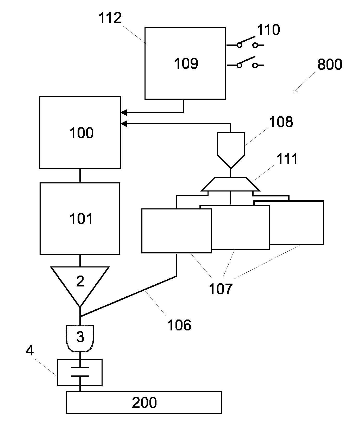
[0085]FIG. 8 shows an embodiment of an active stylus 800 according to the invention. The active stylus 800 comprises an oscillator 1 which continuously generates or emits a signal at a given frequency.

[0086]In the context of the present invention, the expression “continuously emits a signal” means that, once powered and not in stand-by mode, the active stylus 800 transmits a signal without interruption, at least when in operation above a capacitive touch device.

[0087]The signal has an arbitrary phase. In other words the stylus 800 is not synchronised with the capacitive touch device 200. Advantageously the stylus is devoid of a receiver for receiving the capacitive touch device phase information, as a synchronisation with the capacitive touch device 200 is not required.

[0088]In a preferred embodiment the signal is periodic. Any periodic waveform can be selected for this signal, however in a preferred embodiment, this oscillator 1 generates a sinusoidal signal so as to minimize the r...


PUM


Abstract

The invention concerns a capacitive touch system comprising: an active stylus (800) configured so as to continuously emit a signal a capacitive touch device (200) configured to be in a reset phase (1000), followed by a finger touch sensing phase (2000), the finger touches being sensed exclusively during the finger touch sensing phase (2000). The capacitive touch device (200) is configured to sense the signal from the active stylus (800) during the reset phase (1000). The capacitive touch device (200) comprises at least one charge sensor (208, 213) comprising a charge sensor amplifier (305) comprising an input (CSi) and an output (csaout), and a switch (Sw1) between this input (CSi) and this output (csaout). The charge sensor amplifier (305) is arranged for conveying the signal of the active stylus (800) through a non-zero resistance value (Ron) of the switch (Sw1) during the reset phase (1000).

Description

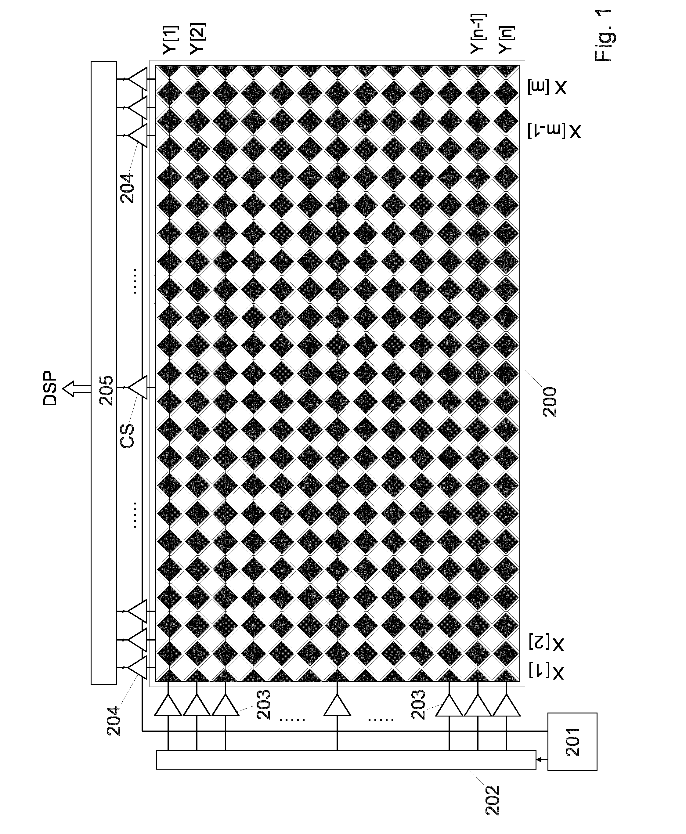
FIELD OF THE INVENTION[0001]The present invention concerns a capacitive touch system, in particular a capacitive touch system comprising an active stylus and a capacitive touch device.DESCRIPTION OF RELATED ART[0002]Capacitive touch devices comprise capacitive sensors used in various application fields in which object presence detections are involved, such as, but not limited to, touch pads, touch panels, touch screens or projective capacitive displays.[0003]When it comes to writing on a capacitive touch device, the use of a stylus (or pen) permits a more comfortable and accurate interaction between the user and an underlying application. A stylus can be passive or active. A passive stylus does not emit any signal: in other words it is an object touching the capacitive touch device and simulating a finger. Although passive styluses are simple, cheap and offer acceptable solutions for sketching, they do not easily allow the differentiation between a pen touch and a finger touch. More...

Claims


Application Information

Patent Timeline
Patent Type & Authority Applications(United States)
IPC IPC(8): G06F3/044G06F3/038G06F3/041G06F3/0354
CPCG06F3/044G06F3/0416G06F3/0383G06F3/03545G06F3/03547G06F3/04166G06F3/04162G06F3/0446G06F3/0442
Inventor BALLAN, HUSSEINBAUSER, PHILIPPE
Owner ADVANCED SILICON
Why Eureka
Try Eureka