Gauge Wheels for a Multi-Section Agricultural Header

a technology of agricultural headers and gauge wheels, applied in the direction of mowers, agriculture tools and machines, agriculture, etc., can solve the problem of only effective system

Active Publication Date: 2016-06-30
MACDON INDS
View PDF15 Cites 44 Cited by
  • Summary
  • Abstract
  • Description
  • Claims
  • Application Information

AI Technical Summary

Problems solved by technology

The gauge wheels serve to minimize any substantial deviations from a central controlled height of the header at the outboard ends of the header, however the system is only effective when used on a rigid header.

Method used


Image

  • Gauge Wheels for a Multi-Section Agricultural Header
  • Gauge Wheels for a Multi-Section Agricultural Header
  • Gauge Wheels for a Multi-Section Agricultural Header

Examples


first embodiment

[0104]Turning now more particularly to FIGS. 6 through 14, the gauge system in this instance further includes a pair of inner gauge wheels 216 which are selectively mounted to the bottom side of the first and second wing frame sections respectively, at the inner ends thereof so as to be approximate to the center frame section.

[0105]At the mounting location of each inner gauge wheel, the header includes an existing support frame 218 formed by an inverted channel member having two side flanges 220 which are upright and in the forward direction at laterally spaced positions. A toe plate 222 spans between bottom edges of the side flanges 220 adjacent the front ends thereof so as to be immediately rearward of the main skid element 16A at the front end of the wing frame sections.

[0106]The side flanges 220 are connected by a top flange 224 at the rear end thereof. The bottom edges of the side flanges include a horizontal flange portion in the forward working direction.

[0107]A pocket 251 is...

second embodiment

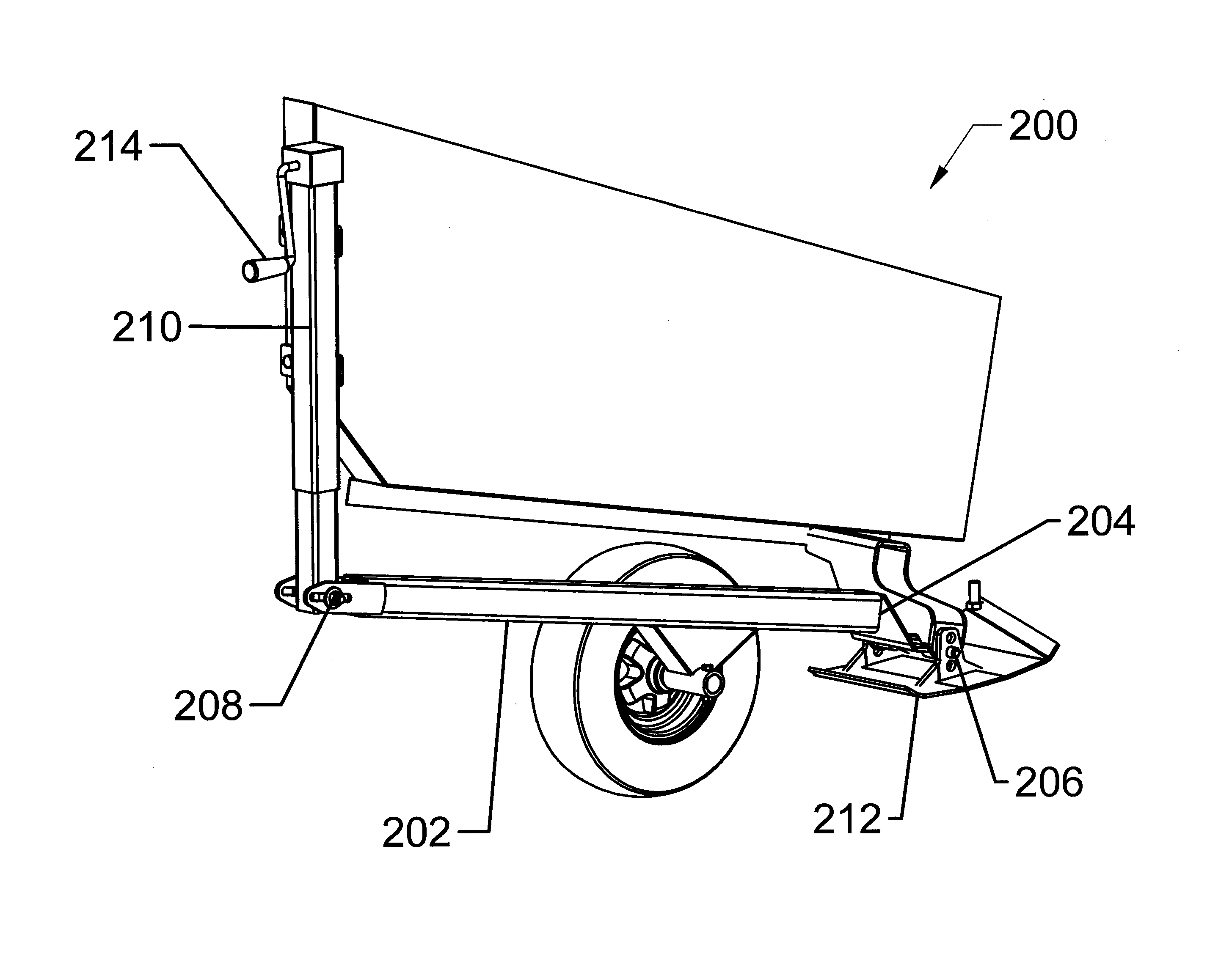
[0115]Turning now to the second embodiment shown in FIG. 15, in this instance, the gauge system according to the present invention again comprises the two outer gauge wheels 200 mounted in the manner described above. The outer gauge wheels however are used with two height sensors 300 instead of the inner gauge wheels 216 in this instance. More particularly, the two height sensors comprised ultrasonic distance sensors mounted on the main frame structure at laterally spaced apart positions in proximity to the center frame section.

[0116]In a preferred arrangement, the two height sensors are mounted at laterally opposed ends of the center frame section and are oriented downwardly to measure distance from the respective mounting location on the main frame structure relative to the ground. The sensors provide an active height signal so as to permit monitoring changes in the height of the main frame structure at the measuring locations as the main frame structure moves upwardly and downwar...


PUM


Abstract

A gauging system is adapted for use with a crop harvesting header of the type having a pair of wing frame portions connected to a center frame portion by a balancing linkage and which is operable in a first mode of operation by engagement of a skid plate of each wing frame potion along the ground. In one embodiment of the invention, the gauging system includes i) outer gauge wheels supporting the outer ends of the wing frame portions such that the skid plate is at a controlled distance from the ground and ii) inner gauge wheels proximate the center frame portion for supporting the inner ends of the wing frame portions such that the skid plate is at a controlled distance from the ground according to a second mode of operation of the header.

Description

[0001]This application claims the benefit under 35 U.S.C. 119(e) of U.S. provisional application Ser. No. 62 / 097,202, filed Dec. 29, 2014.FIELD OF THE INVENTION[0002]The present invention relates to a header for a combine harvester where the header includes ground engaging gauge wheels to provide stability to the header when cutting off the ground.BACKGROUND[0003]Headers for combine harvesters are typically mounted on the feeder house of the combine to allow some floating action of the header relative to the feeder house so that the cutter bar can rest on the ground and float over the ground responsive to ground contours in a cutting action. To optimally follow ground contours, various attempts have been made to introduce some flexibility into the header.[0004]U.S. Pat. No. 6,675,568 by Patterson et al discloses one example of a multi-section header with a flexible crop cutting knife for this purpose. The main frame structure of the header is formed in multiple sections including a ...

Claims


Application Information

Patent Timeline
Patent Type & Authority Applications(United States)
IPC IPC(8): A01D41/14A01D61/00A01D34/14
CPCA01D41/145A01D2101/00A01D61/002A01D34/14A01D41/14
Inventor NEUDORF, BRENT
Owner MACDON INDS
Why Eureka
Try Eureka