Cleat assembly for clipless pedal

a technology of clipless pedals and assemblies, applied in the direction of vehicle components, mechanical equipment, footwear, etc., can solve the problems of unsatisfactory wear of the bottom plate, increased labor and cost, and difficulty in engaging or disengaging the spring clip to/from the pedal, so as to achieve the effect of enhancing manufactur

Active Publication Date: 2011-02-01
WAHOO FITNESS LLC
View PDF19 Cites 25 Cited by
  • Summary
  • Abstract
  • Description
  • Claims
  • Application Information

AI Technical Summary

Benefits of technology

[0012]In alternative embodiments of the invention, the cleat assembly includes a unitary cap preferably disposed over substantially the entire bottom surface of the second plate. The unitary cap engages the ground when the user walks thereon and incorporates a molded elastomeric material, e.g., polyurethane. The unitary cap helps the user's foot to roll comfortably when the user walks, and helps keep the second plate from scratching the bicycle pedal. The second plate is configured to have two hooks that engage the first plate, while the unitary cap is configured to have two tabs that engage the first plate. Alternatively, the unitary cap is configured to have four tabs that engage the first plate. The hooks and tabs secure the second plate and unitary cap to the first plate, keeping the first plate, second plate, and spring clip secured together both prior to the initial installation of the cleat assembly and also in the event that the user detaches the cleat assembly from the shoe. This feature makes both the initial installation and any re-installation of the cleat assembly easier and reduces the possibility that the user might misplace parts of the cleat assembly while it is detached from the shoe.
[0014]The size of the float angle can be adjusted by selectively rotating the one or more set screws, to vary the size of the space that receives the spring clip's finger. Advantageously, each set screw is received within a threaded aperture that is defined by confronting surfaces of the first and second plates. The first plate preferably comprises a molded plastic material, and the second plate preferably comprises a metallic material, preferably steel. In addition, manufacturability is enhanced by configuring only the confronting surface of the first plate to be threaded; the confronting surface of the second plate can remain unthreaded.
[0015]In one embodiment of the invention, two holes are formed in the confronting surfaces of the second plate that retain the two set screws. The two holes allow the two set screws to contact the elastomeric material of the cap or caps, inhibiting the set screws from working their way loose from the cleat assembly. In this way, the holes act like threadlockers, helping to keep the set screws secured in the cleat assembly.
[0016]Other screws secure the first and second plates together. In a preferred embodiment of the invention, the cap or caps are configured to have a plurality of openings therein, each of the plurality of openings being configured to receive the head of at least one screw. The openings in the cap or caps are sized so that the screw heads contact the sidewalls of the openings, inhibiting the screws from working their way loose. In this way, the openings act like threadlockers, helping to keep the screws secured in place.

Problems solved by technology

This direct engagement also has led to undesired wear of the bottom plate.
In the past, improper over-tightening of the bottom plate over the spring housing has sometimes unduly restricted free flexing movement of the spring clip, thus sometimes making it more difficult to engage or disengage the spring clip to / from the pedal.
This has been found to be unduly labor-intensive and expensive.
This made re-installation of the cleat assembly more difficult and raised the possibility that the user might misplace parts of the cleat assembly while it was detached from the shoe.
In the past, the set screws and other screws present in cleat assemblies of this particular kind had a tendency to work their way loose during use of the cleat assembly.
The use of a separate adhesive has been found to be unduly labor-intensive and undesirable.

Method used


Image

  • Cleat assembly for clipless pedal
  • Cleat assembly for clipless pedal
  • Cleat assembly for clipless pedal

Examples


Embodiment Construction

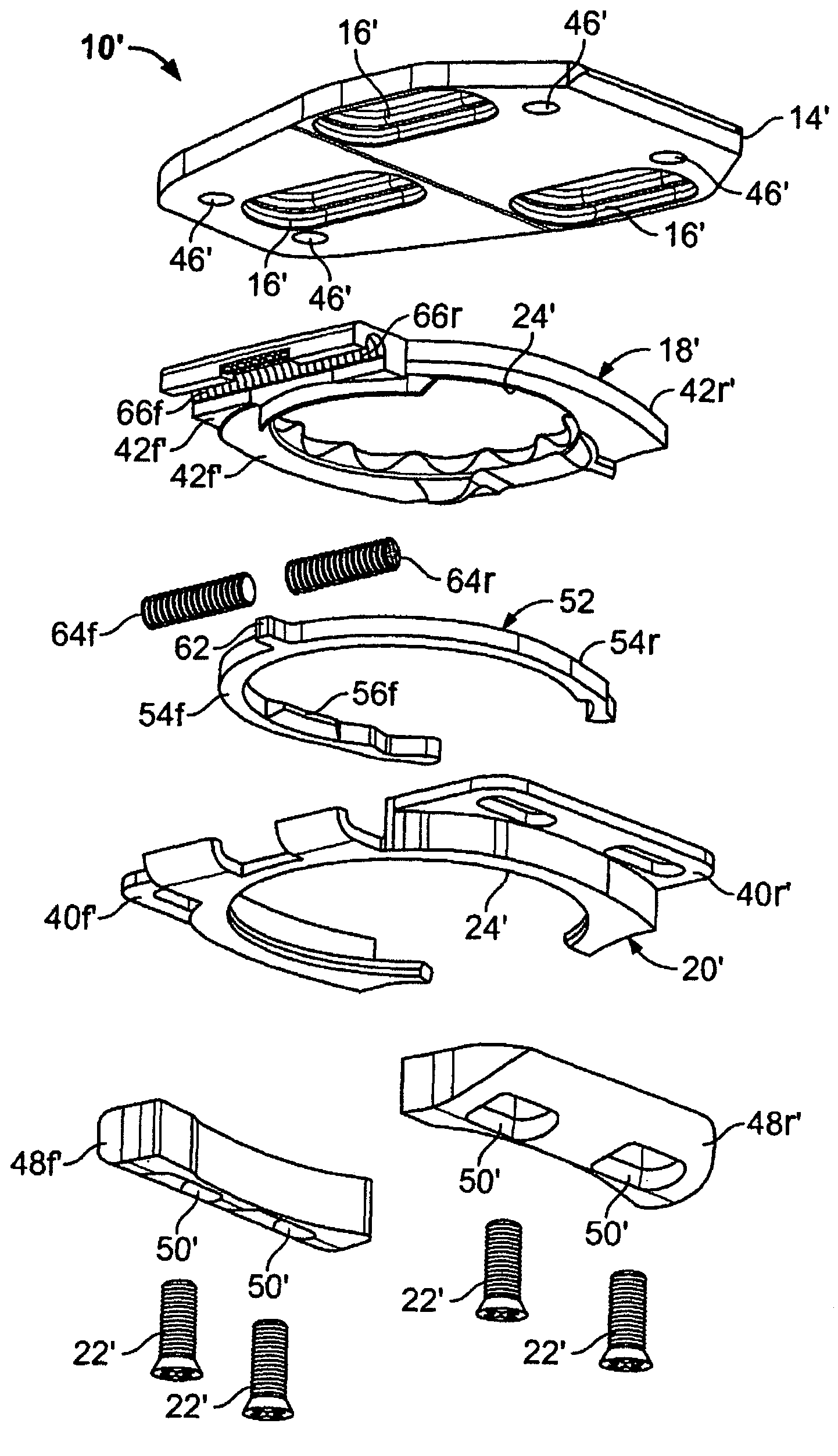
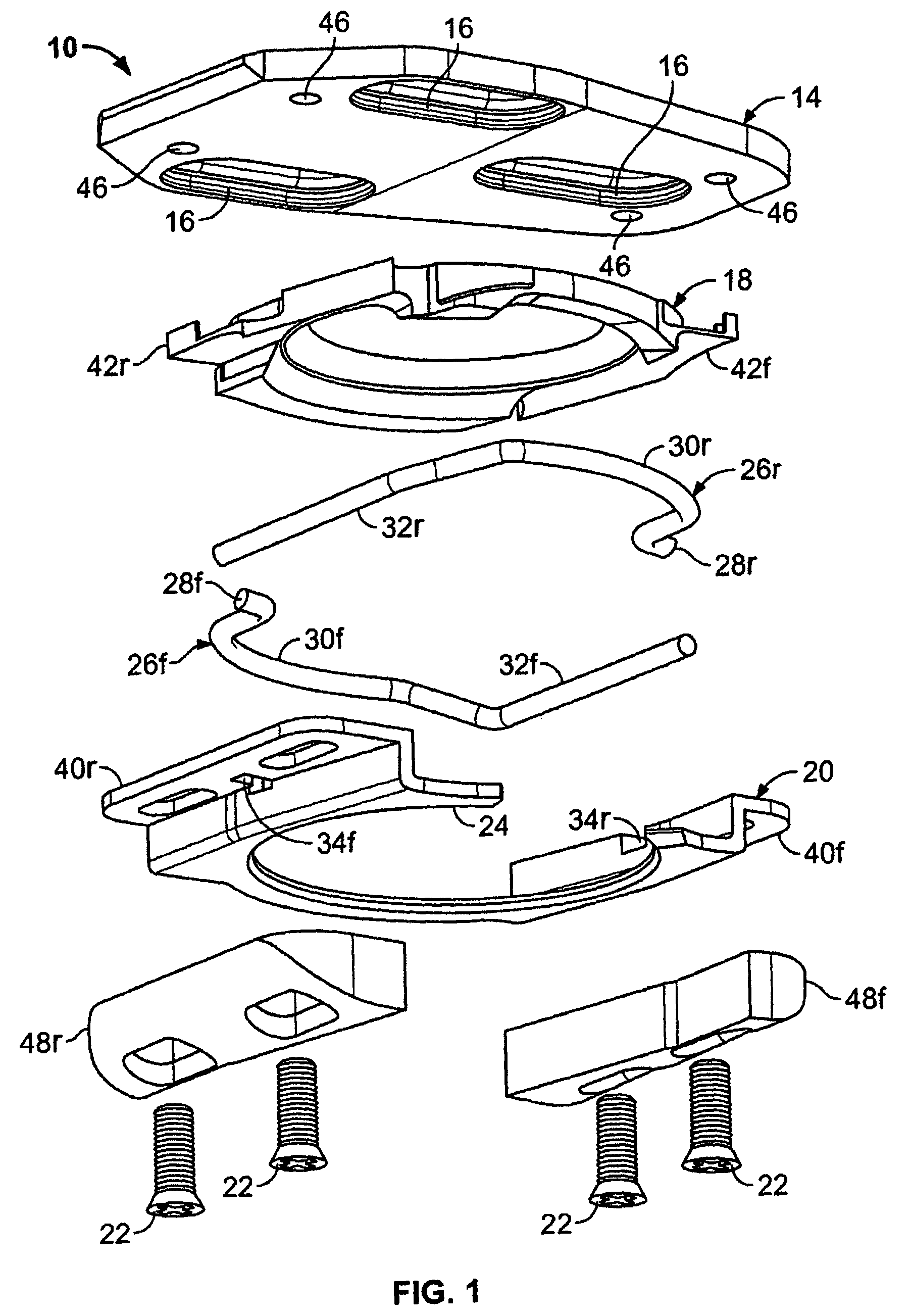
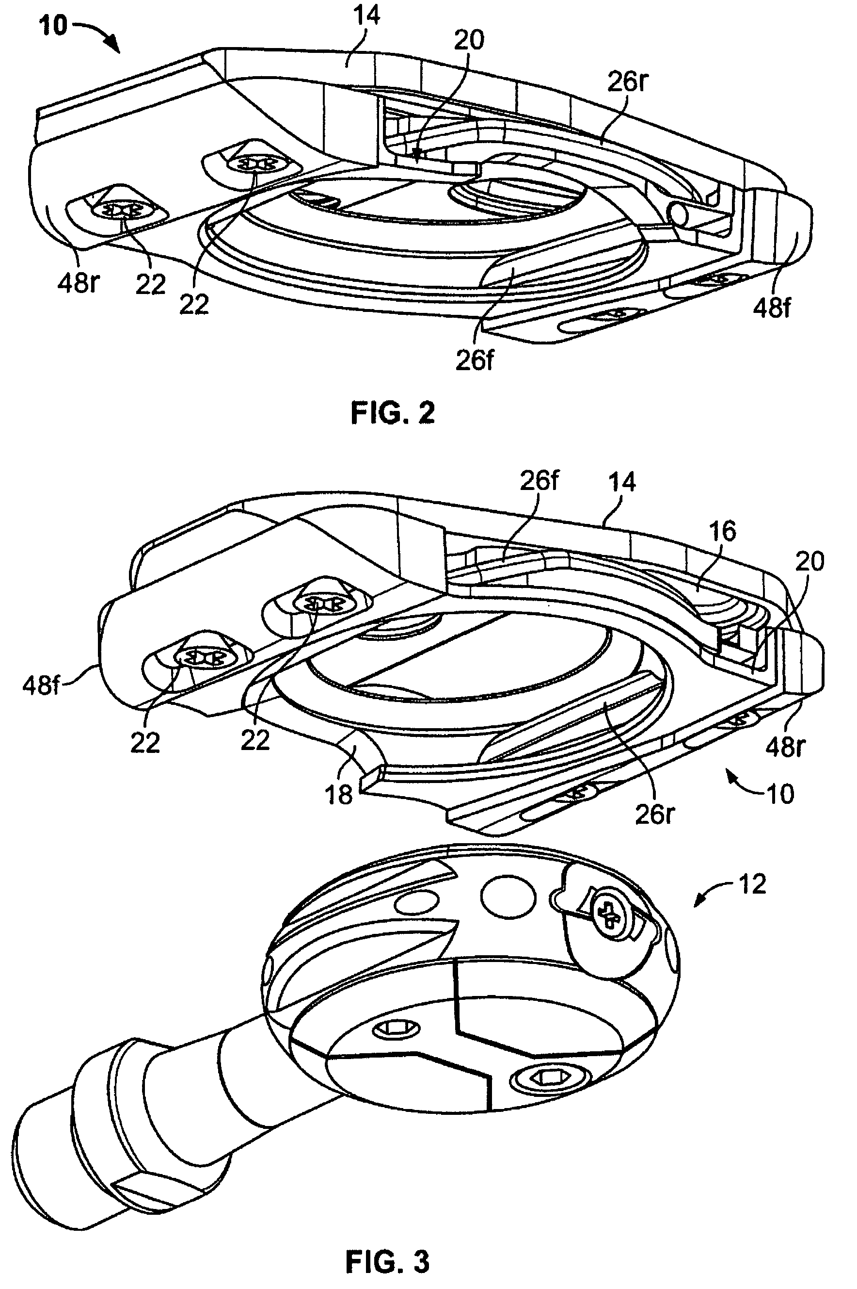
[0044]With reference now to the illustrative drawings, and particularly to FIGS. 1-4, there is shown a first embodiment of a cleat assembly 10 in accordance with the invention, configured for attachment to the sole of a user's shoe (not shown) and for releasable securement to a bicycle pedal 12 (FIGS. 3 and 4). The particular cleat assembly depicted is configured for attachment to the user's left shoe, but it will be appreciated that a similar cleat assembly could be oppositely configured for attachment to the user's right shoe. The cleat assembly includes a plastic base plate 14 configured to be secured to the shoe's sole (not shown) by screws (not shown) extending through three elongated openings 16, and it further includes a plastic spring housing 18 and a steel bottom plate 20 configured to be secured, together, by four screws 22 to the plastic base plate 14. The spring housing 18 and bottom plate 20, together, define a circular central opening 24 sized and shaped to conformably...


PUM


Abstract

An improved cleat assembly is disclosed, the assembly containing one or more spring clips configured for releasably securing the assembly to a bicycle pedal or the like. Specifically, the cleat assembly is configured such that an improper over-tightening of the cleat onto the sole of a user's shoe has substantially no effect on the free flexing of the spring clip while it is engaging or disengaging to / from the pedal. In addition, the cleat assembly incorporates one or more soft elastomeric caps that frictionally engage the ground when the user walks about, to provide improved traction and to eliminate undesired wear of critical assembly components. Further, for embodiments of cleat assemblies of the kind incorporating one or more adjustable set screws for adjusting the assemblies' float angles, threaded apertures for the set screws are formed by the confronting surfaces of a plastic upper plate and a metallic bottom plate, wherein the threads are formed only in the plastic upper plate. This allows the upper plate to be conveniently formed of an injection-molded plastic material and the bottom plate to be conveniently stamped from a piece of sheet metal.

Description

CROSS REFERENCE TO RELATED APPLICATIONS[0001]This is a continuation-in-part of U.S. application patent Ser. No. 11 / 250,911, filed on Oct. 13, 2005, the entire contents of which are herein incorporated by reference.BACKGROUND OF THE INVENTION[0002]This invention relates generally to cleat assemblies configured for releasable securement to pedals for bicycles and the like, and, more particularly, to cleat assemblies incorporating flexible spring clips for releasable engagement with the pedals.[0003]Cleat assemblies of this particular kind typically include a spring housing and an overlaying bottom plate configured to be attached to the sole of a user's shoe. The spring housing and bottom plate, together, define a central opening sized and configured to conformably receive a pedal. The spring housing supports one or more spring clips adjacent to the central opening, for engaging and releasably retaining the pedal.[0004]When the cleat assembly is disengaged from a pedal and the user is ...

Claims


Application Information

Patent Timeline
Patent Type & Authority Patents(United States)
IPC IPC(8): A43B5/14
CPCA43B5/14B62M3/086Y10T74/217
Inventor BRYNE, RICHARD M.
Owner WAHOO FITNESS LLC
Why Eureka
Try Eureka