Joint power control device

a power control device and joint technology, applied in the field of joint power control devices, can solve the problems of increasing the weight or size of the spring, the space required for the operation of the spring the device for imparting the power to the knee joint mechanism tends to become larger, so as to reduce the place of the power transmission movable mechanism

Active Publication Date: 2016-06-30
HONDA MOTOR CO LTD
View PDF6 Cites 20 Cited by
  • Summary
  • Abstract
  • Description
  • Claims
  • Application Information

AI Technical Summary

Benefits of technology

[0041]In the joint mechanism according to the eleventh aspect of the invention, the amount of a change in the amount of displacement, i.e. the amount of rotation, of the first link when a leg of a person wearing the first member and the second member is bent to a maximum from a stretched state can be controlled to be relatively small. Hence, t

Problems solved by technology

This inconveniently leads to an increased weight or size of the spring.
Hence, the space required for the operation of the spring tends to become larger.
Accordingly, the d

Method used


Image

  • Joint power control device
  • Joint power control device
  • Joint power control device

Examples


Embodiment Construction

[0057]An embodiment of the present invention will be described below with reference to FIG. 1 to FIG. 9.

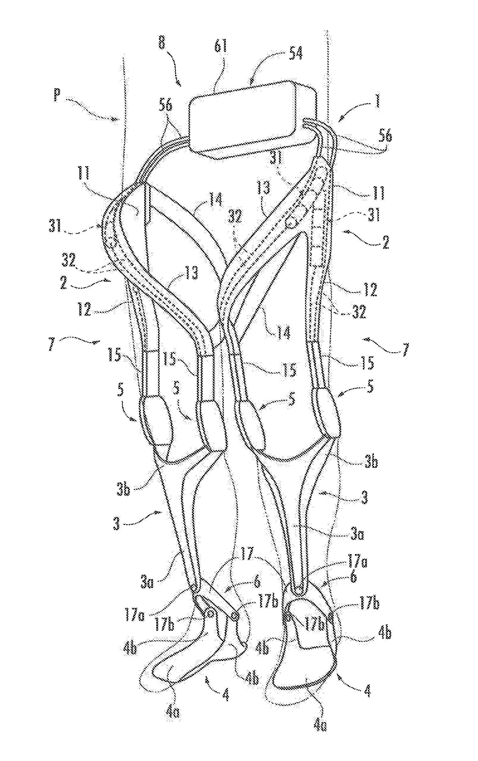
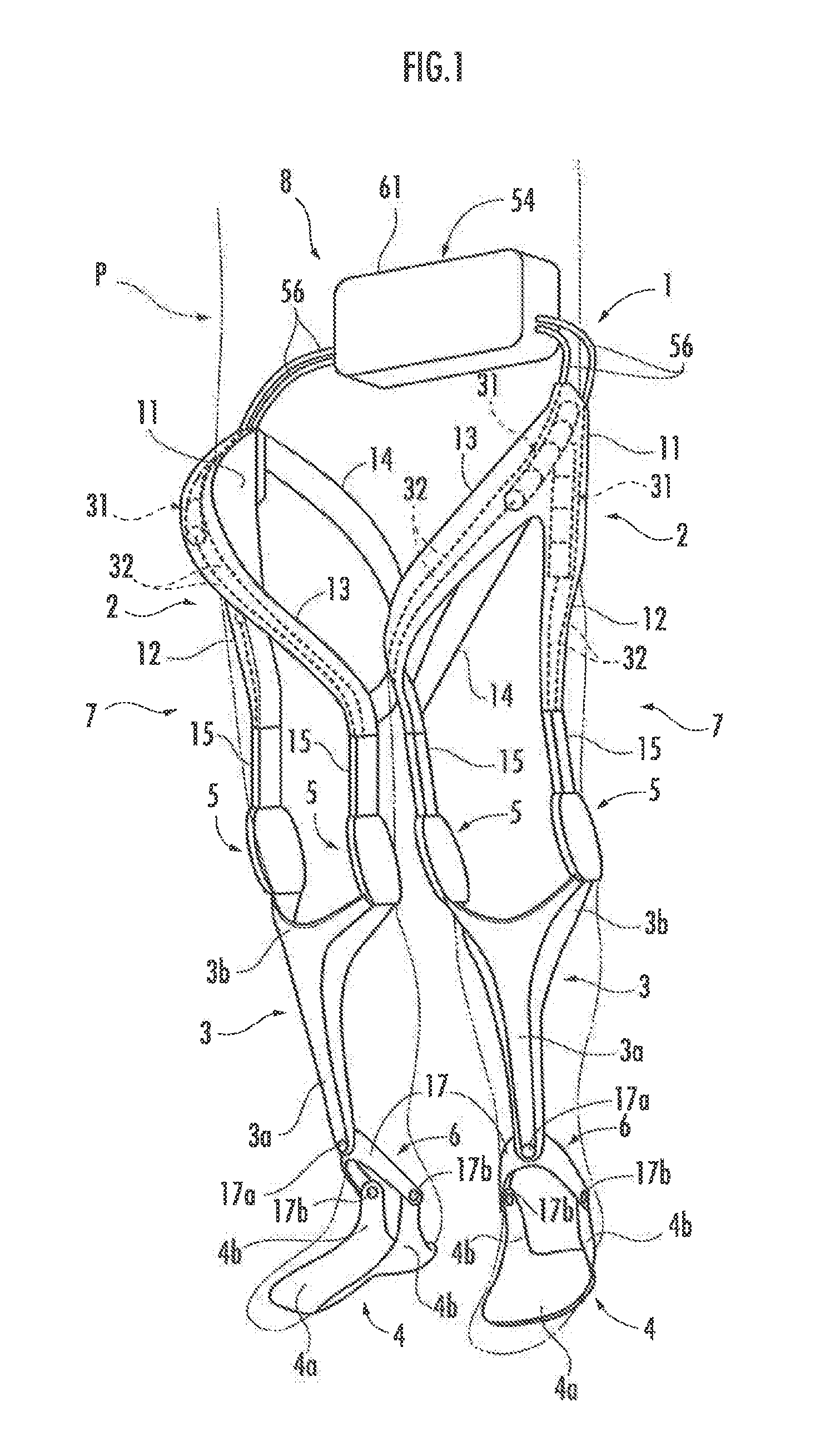
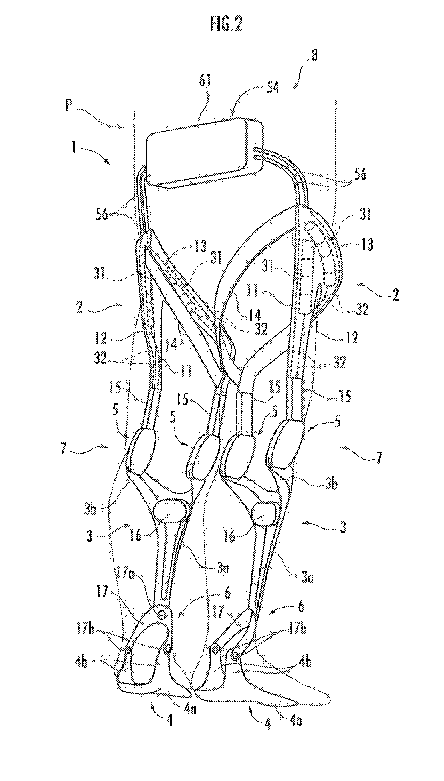
[0058]Referring to FIG. 1 to FIG. 3, a joint power control device 8 illustrated in the present embodiment is a device provided in a motion assisting apparatus 1 to be attached to a person to be assisted P in order to assist the motions of his or her legs mainly when the person to be assisted P walks.

[0059]The motion assisting apparatus 1 has, for each leg of the person to be assisted P, a leg link mechanism 7 that includes a thigh frame 2, a crus frame 3, a foot frame 4, and a pair of knee joint mechanisms 5, 5, which connect the thigh frame 2 and the crus frame 3 in a relatively displaceable manner, and an ankle joint mechanism 6, which connects the crus frame 3 and the foot frame 4 in a relatively displaceable manner, and a joint power control device 8 that controls a joint power, which is a force to be imparted to the knee joint mechanisms 5, 5 of the leg link mechanism 7. In t...


PUM


Abstract

A present invention provides a joint power control device. A joint interlock displacement part (52) of a power transmission movable mechanism (53), which is comprising of a moving pulley (51) and the like, is connected to a joint mechanism (5) disposed between a first member (2) and a second member (3). A flexible lengthy member (32), which is one of two flexible lengthy members (32, 32) extending from the power transmission movable mechanism (53), is connected to a control mechanism (54) that controls the movement of the flexible lengthy member (32). Further, an elastic structure (31) is engaged with the other flexible lengthy member (32).

Description

FIELD OF THE INVENTION[0001]The present invention relates to a joint power control device adapted to control the force, i.e. the joint power, to be imparted to a joint mechanism which connects two members in a relatively displaceable manner.DESCRIPTION OF THE RELATED ART[0002]As a device provided with a joint mechanism that connects two members in a relatively displaceable manner, there has hitherto been known, for example, a motion assisting apparatus adapted to be attached to the legs of a person to be assisted and to generate power for assisting the bending and stretching motions of the legs. For example, Japanese Patent Application Laid-Open No. 2014-508010 (hereinafter referred to as “Patent Document 1”) discloses a motion assisting apparatus provided with thigh frames and crus frames to be attached to the thighs and the cruses, respectively, of the legs of a person to be assisted, and springs. The motion assisting apparatus uses the elastic forces of the springs to apply power...

Claims


Application Information

Patent Timeline
IPC IPC(8): A61F2/68A61H3/00
CPCA61H3/00A61F2/68A61F2/70A61H1/0255A61H2201/0103A61H2201/1215A61H2201/1463A61H2201/149A61H2201/1623A61H2201/164A61H2201/1645A61H2201/165A61H2201/1676
Inventor IKEDO, YOSUKETAKENAKA, TORUGOMI, HIROSHISODEYAMA, YOSHINAOKATAGIRI, KENICHI
Owner HONDA MOTOR CO LTD
Why Eureka
Try Eureka