Work vehicle

a technology for working vehicles and bending parts, which is applied in the direction of machine supports, other domestic objects, light and heating equipment, etc., can solve the problems of increasing the vibration of the side view mirror due to the mounting plates, and achieve the rigidity of the bending portion, and the weight of the other lateral end portion

Inactive Publication Date: 2016-06-30
YANMAR POWER TECHNOLOGY CO LTD
View PDF6 Cites 13 Cited by
  • Summary
  • Abstract
  • Description
  • Claims
  • Application Information

AI Technical Summary

Benefits of technology

[0011]As the effects of the present invention, the following advantageous effects are provided.
[0012]According to the present invention, while the rigidity of one lateral end portion (the lateral end portion of the cabin) and the rigidity of the bending portion of the support arm are secured, the weight of the other lateral end portion (the lateral end portion of the side view mirrors) is reduced. Accordingly, the side view mirrors can be arranged at the arbitrary positions while the vibration of the side view mirrors is reduced.
[0013]According to the present invention, the rigidity of the one lateral end portion of the support arm is further improved by the front working light cover provided on one lateral end portion (the lateral end portion of the cabin) of the support arm. Accordingly, the side view mirrors can be arranged at the arbitrary positions while the vibration of the side view mirrors is reduced.
[0014]According to the present invention, the side view mirrors in which the side-marker lights are provided are arranged at the positions separated from the cabin. Accordingly, the width and height of the work vehicle can be simultaneously represented while the field of vision in the rear is secured.

Problems solved by technology

However, in the work vehicle, the mounting plates themselves are not reinforced, so that there is a possibility that when the side view mirrors are arranged at positions separated from the cabin, the vibration of the side view mirrors is increased due to the mounting plates.

Method used


Image

  • Work vehicle
  • Work vehicle
  • Work vehicle

Examples


Embodiment Construction

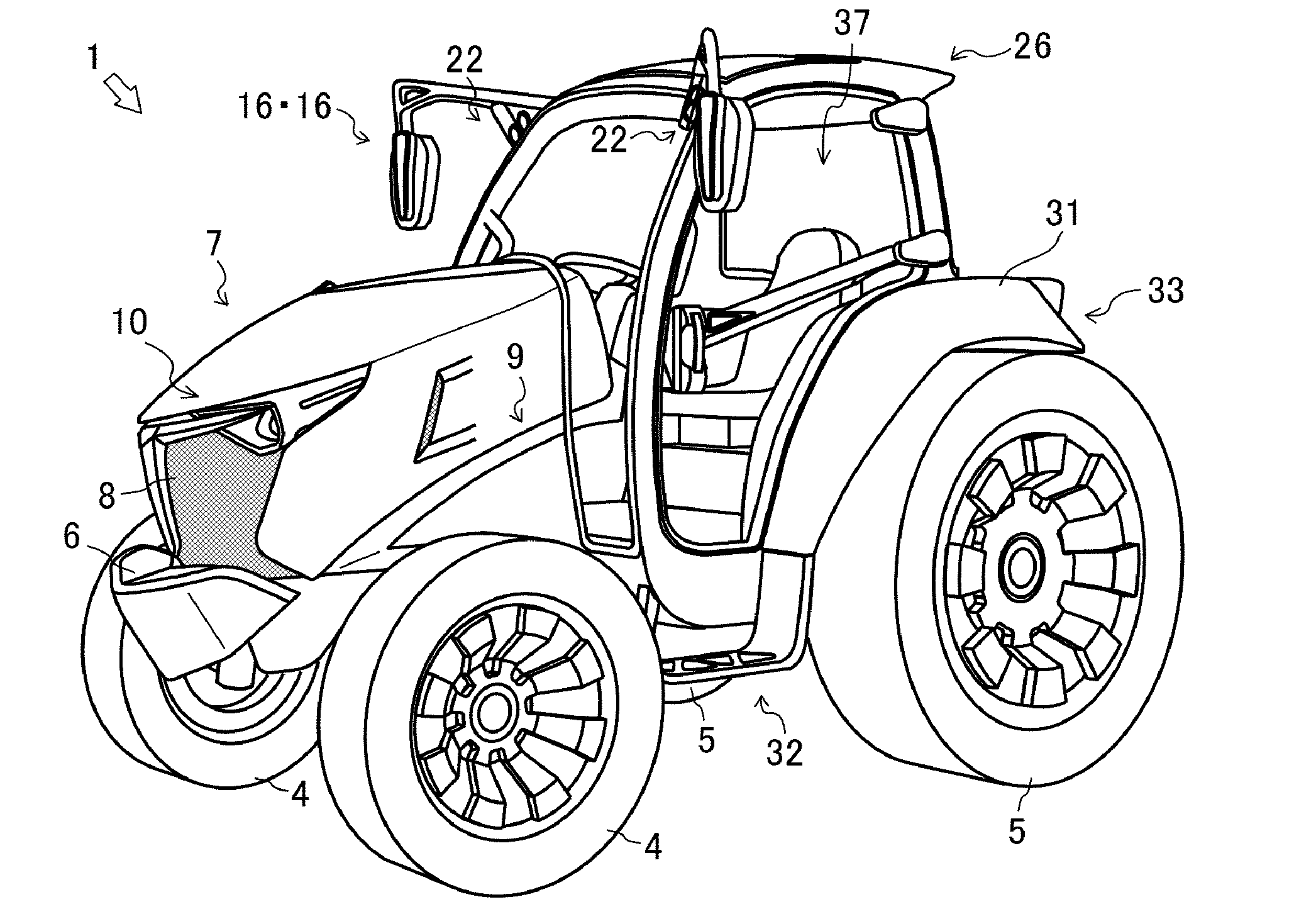
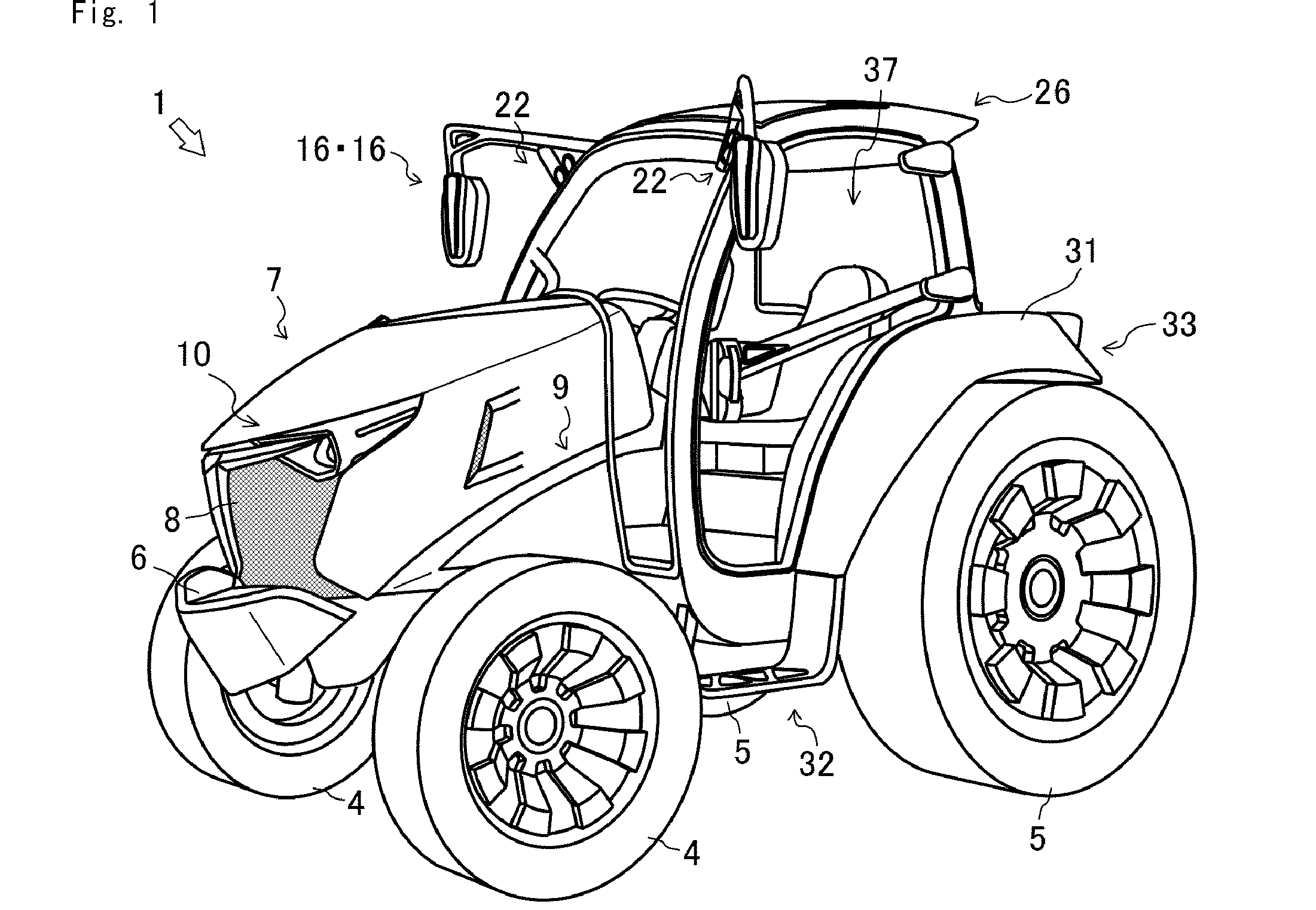
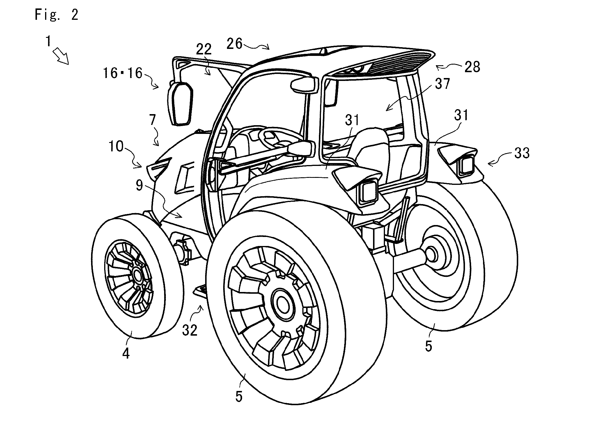
[0043]Hereinafter, a tractor 1 of an embodiment of a work vehicle according to the present invention will be described. In the following description, the front, rear, right and left directions are defined based on the advancing direction of the tractor 1 as the front.

[0044]First, the entire constitution of the tractor 1 according to the present invention will be described referring to FIGS. 1 to 8. It is noted that the work vehicle according to the present invention is not limited to the tractor 1, but can be applied to vehicles across the board, such as other agricultural vehicles, construction vehicles, and industrial vehicles.

[0045]As illustrated in FIGS. 1 and 2, the tractor 1 is equipped with various work machines (rotaries and the like) and performs various works. Regarding the tractor 1, an engine 3, a hood 7, a transmission case, a front axle, a rear axle, each of which is not illustrated, a cabin 26, and a drive operating unit 37 are arranged on a machine body frame 2 of wh...


PUM


Abstract

It is an object to provide a work vehicle being capable of arranging side view mirrors at arbitrary positions while reducing the vibration of the side view mirrors. Regarding a tractor, which is a work vehicle in which a mirror portion of a side view mirror is provided on the other end of a support arm whose one end is fixed on a cabin for covering a drive operating unit, the support arm is bent in a midway portion, and a beam is integrally formed with the support arm in such a manner as to sandwich a bending portion, and a cross-sectional area of a cross section vertical to the axial direction of the support arm is configured to be reduced as the support arm advances from the one end to the other end thereof.

Description

CROSS REFERENCE TO RELATED APPLICATIONS[0001]This is the U.S. national stage of application No. PCT / JP2014 / 066390, filed on Jun. 20, 2014. Priority under 35 U.S.C. §119(a) and 35 U.S.C. §365(b) is claimed from Japanese Application No. 2013-154030, filed Jul. 24, 2013, the disclosure of which is also incorporated herein by reference.TECHNICAL FIELD[0002]The present invention relates to a work vehicle.BACKGROUND ART[0003]Conventionally, regarding passenger work vehicles, there have been known work vehicles in which side view mirrors are provided in a cabin that covers a drive operating unit. In the work vehicle, the side view mirrors are mounted on a frame of the cabin via mounting plates. For example, Patent Literature 1 discloses the above-mentioned work vehicle.[0004]Regarding the work vehicle in Patent Literature 1, the side view mirrors are mounted on the frame of the cabin via the mounting plates. Furthermore, the proximity of the mounting plates of the frame of the cabin is rei...

Claims


Application Information

Patent Timeline
Patent Type & Authority Applications(United States)
IPC IPC(8): B60R1/12B60Q1/32B60Q1/26B60Q1/18B60R1/06B60Q1/00
CPCB60R1/1207B60R1/06B60Q1/32B60Q1/2665B60Q1/18B60Q1/0035B60Q1/0041B60Q1/24B60Q1/2607B60Q2800/20
Inventor KAWASHIRI, SHINYAOKUYAMA, KIYOYUKI
Owner YANMAR POWER TECHNOLOGY CO LTD
Why Eureka
Try Eureka