Bus end arc interrupter

a technology of interrupter and bus end, which is applied in the direction of substation/switching arrangement casing, non-enclosed substation, substation, etc., can solve the problems of high cost, high cost, and high cost, and achieve the effect of reducing the risk of arcing, and reducing the duration of the arcing even

Active Publication Date: 2016-06-30
SCHNEIDER ELECTRIC USA INC
View PDF2 Cites 8 Cited by
  • Summary
  • Abstract
  • Description
  • Claims
  • Application Information

AI Technical Summary

Benefits of technology

[0008]The arc transit zone is designed to receive the arc and provide a shaped path for it to travel essentially unimpeded within the enclosure toward the terminal ends of the conductors. A nonconductive insulated phase barrier resembling a nonconductive busbar may be disposed within the arc transit zone for shaping the arc. The insulated phase barrier may extend along a longitudinal axis of the enclosure up to the arc interruption zone substantially equidistant between the parallel conductors. The phase barrier has a terminal end that ends substantially even with or a predefined distance beyond the terminal ends of the conductors, but a width that is smaller than the widths of the conductors by a predefined amount on each side. A substantially C-shaped channel member may be provided in the transit zone adjacent to the sides of the phase barrier and extending in a longitudinal direction along the phase barrier to define a C-shaped corridor on each side of the phase barrier. This forces any arc entering the arc interrupter to assume an arcuate or serpentine shape in the side corridors, thus stretching and increasing the voltage of the arc. The increased voltage reduces the arc current, resulting in lower total energy generated by the arc. A convergence device resembling a cone may be disposed at the entrance of the enclosure to help funnel the arc into the arc interrupter. Backflow valves may also be mounted near the entrance of the enclosure to help keep hot gasses produced by the arc from escaping backward through the entrance.

Problems solved by technology

When an arc jumps from one conductor to another across an air gap, it can produce extremely hot gasses, vaporized metals / polymers, and other harmful byproducts.
Concerns with active techniques may include higher cost, nuisance breaker trips, speed, and undetected system failures.
Neither of the above passive methods limits the duration of the arcing event.

Method used


Image

  • Bus end arc interrupter
  • Bus end arc interrupter
  • Bus end arc interrupter

Examples


Embodiment Construction

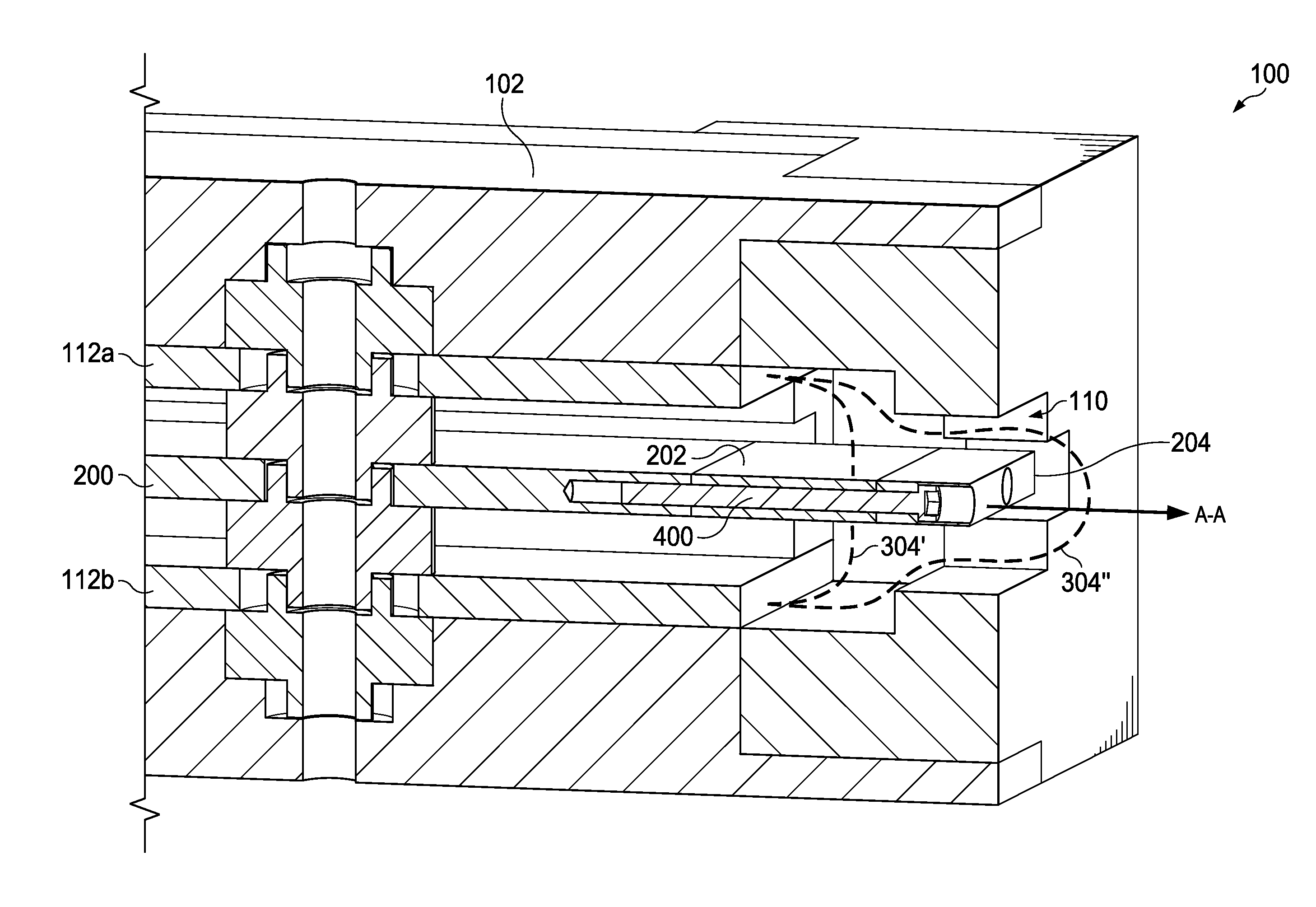
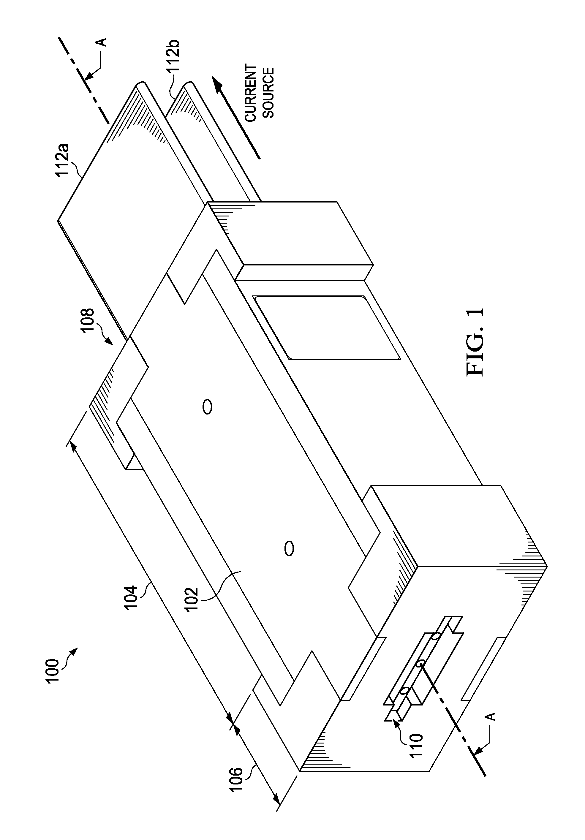
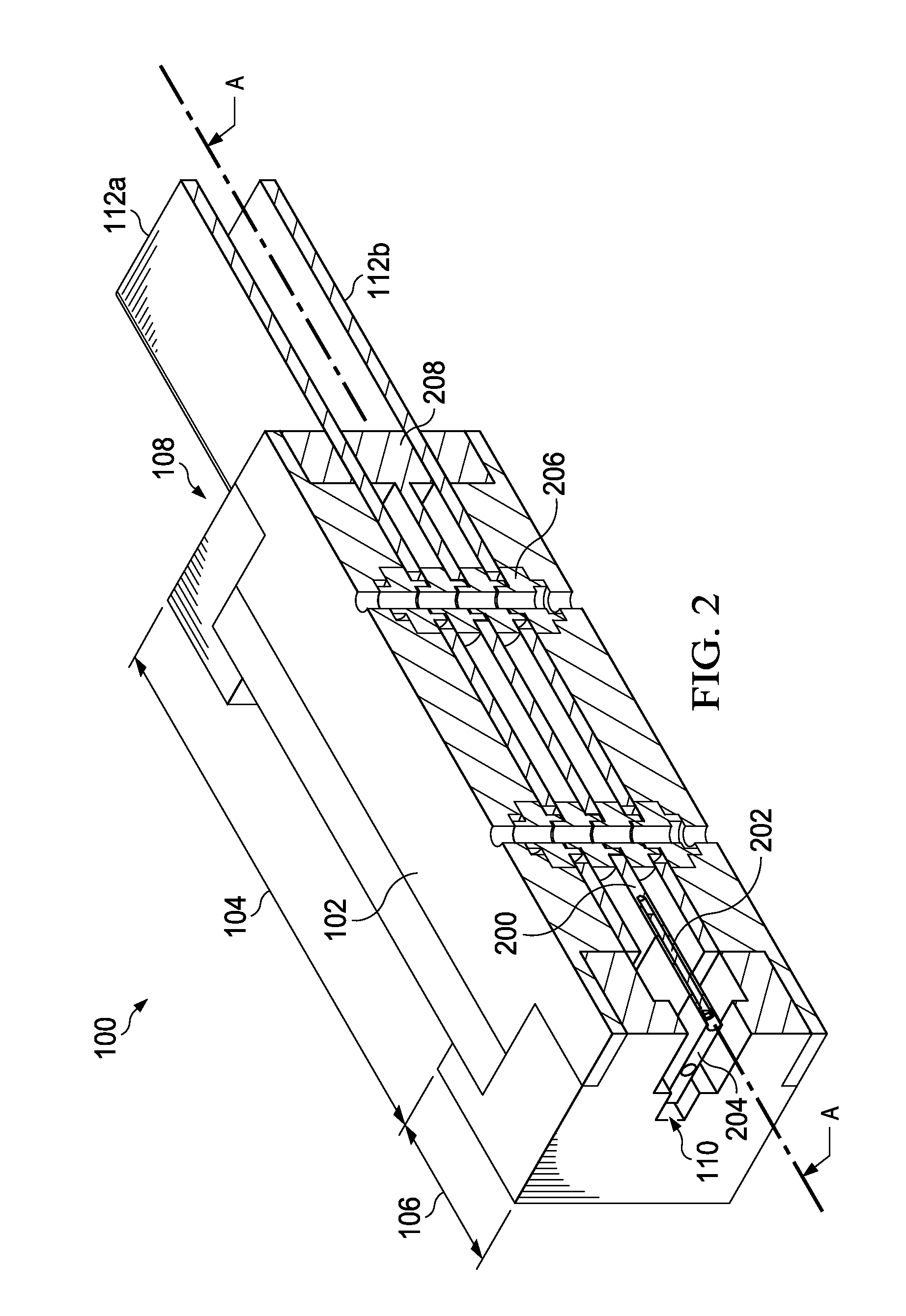
[0006]The embodiments disclosed herein are directed to methods and systems for controlling and limiting the damage caused by arcs formed on exposed conductors such as between two or more busbars or a busbar and ground in electrical distribution equipment. The methods and systems take advantage of the tendency for electromagnetic forces to push an arc in a direction away from a current source. This phenomenon compels an arc formed between two parallel conductors to travel toward the terminal ends of the conductors or the ends that are opposite the current source. An arc interruption device, or arc interrupter, may then be placed over the terminal ends of the conductor, thus forcing the arc to enter the arc interrupter as it travels toward the conductor terminal ends. Inside the arc interrupter, the shape of the arc is conformed to geometries designed to stretch and lengthen the arc, and thereby attenuate its current and temperature to the point where it can no longer be sustained and...


PUM


Abstract

Method and system for controlling and limiting the damage caused by arcs formed on exposed conductors in electrical distribution equipment involve using the tendency of an arc to move in a direction away from a current source and toward the terminal ends of the conductors. An arc interruption device, or arc interrupter, is placed over the terminal ends of the conductor to capture the arc as it travels toward the terminal ends of the conductors. Within the arc interrupter, the shape of the arc is conformed to geometries designed to stretch and extend the arc to the point where it can no longer be sustained and is extinguished.

Description

CROSS-REFERENCE TO RELATED APPLICATIONS[0001]The present application is related in subject matter to commonly-assigned U.S. application Ser. No. 13 / 452,145, entitled “Passive Arc Management System with a Flue Chamber,” filed 20 Apr. 2012; International Application No. PCT / US13 / 50797, entitled “Internal Arc Management and Ventilation for Electrical Equipment,” filed 17 Jul. 2013; U.S. application Ser. No. 14 / 501,946, entitled “Passive Arc Protection for Main Breaker Line Side Power Conductors,” filed Sep. 30, 2014; U.S. application Ser. No. ______, entitled “Method for Treating Internal Arcs,” filed concurrently herewith; and U.S. application Ser. No. ______, entitled “Panelboard Power Bus with Arc Transfer for Passive Arc Control,” filed concurrently herewith (respectively, Docket Nos. CRC-0266, CRC-0275, CRC-0299, CRC-0301, and CRC-0304), all of which are incorporated herein by reference in their entirety.FIELD OF THE INVENTION[0002]The present invention relates generally to method...

Claims


Application Information

Patent Timeline
Patent Type & Authority Applications(United States)
IPC IPC(8): H02B13/025H02B1/56H02B1/20
CPCH02B13/025H02B1/56H02B1/20H02B1/26H01H9/342H01H85/44H01T4/10H02G5/00H02B1/21H01H9/44H01T4/02H01T4/04H01T4/14
Inventor FABER, TIMOTHYWOODSON, CAMERONRIVAL, MARCGONNET, JEAN-PAUL
Owner SCHNEIDER ELECTRIC USA INC
Why Eureka
Try Eureka