Biological information measuring module and biological information measuring apparatus
a biological information and measuring module technology, applied in the field of biological information measuring modules and biological information measuring apparatuses, can solve the problems of inaccurate measurement and the size of the measuring apparatus becoming larger, and achieve the effects of improved accuracy, excellent portability and small siz
- Summary
- Abstract
- Description
- Claims
- Application Information
AI Technical Summary
Benefits of technology
Problems solved by technology
Method used
Image
Examples
first embodiment
1. Overall Configuration Example of Biological Information Measuring Apparatus
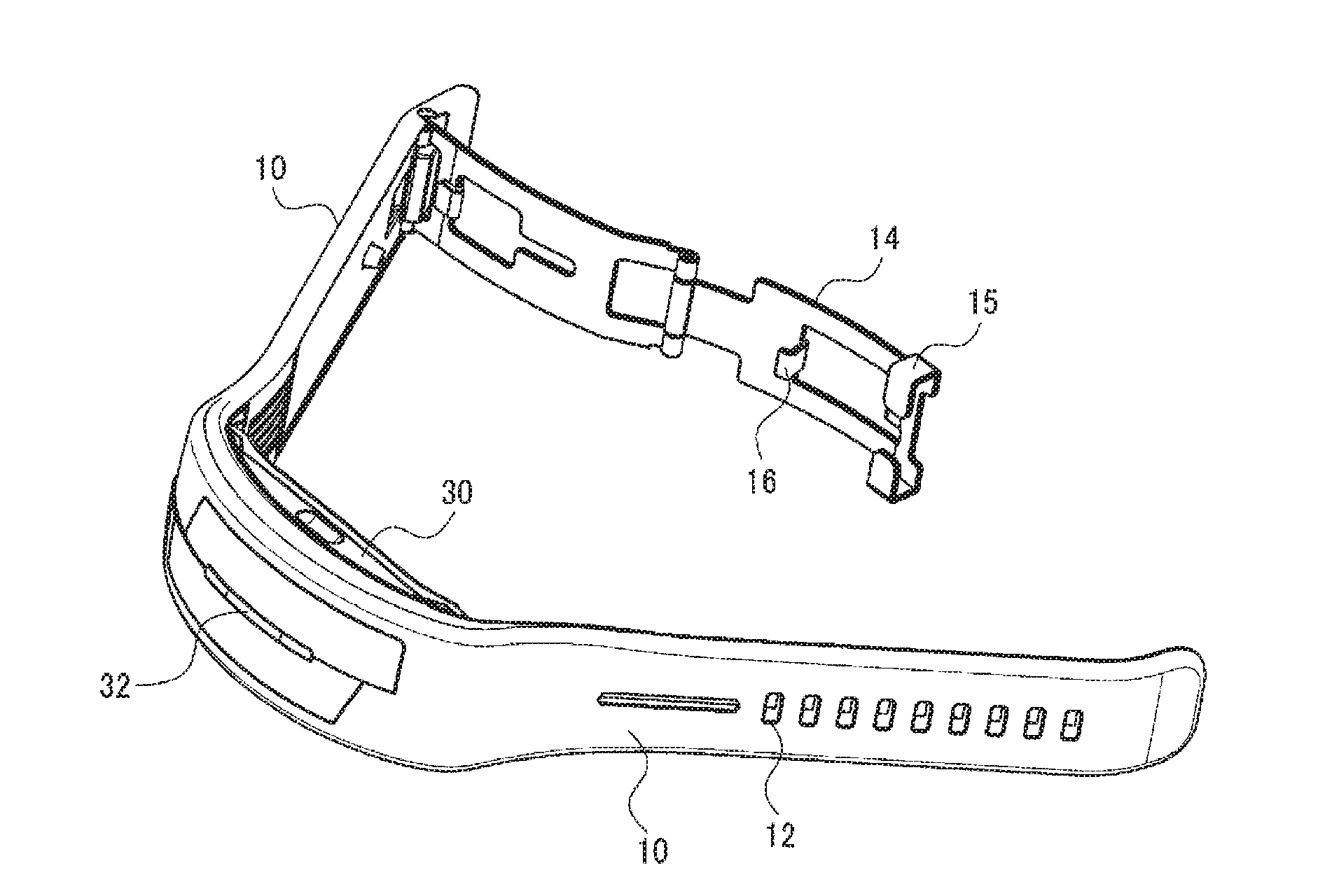
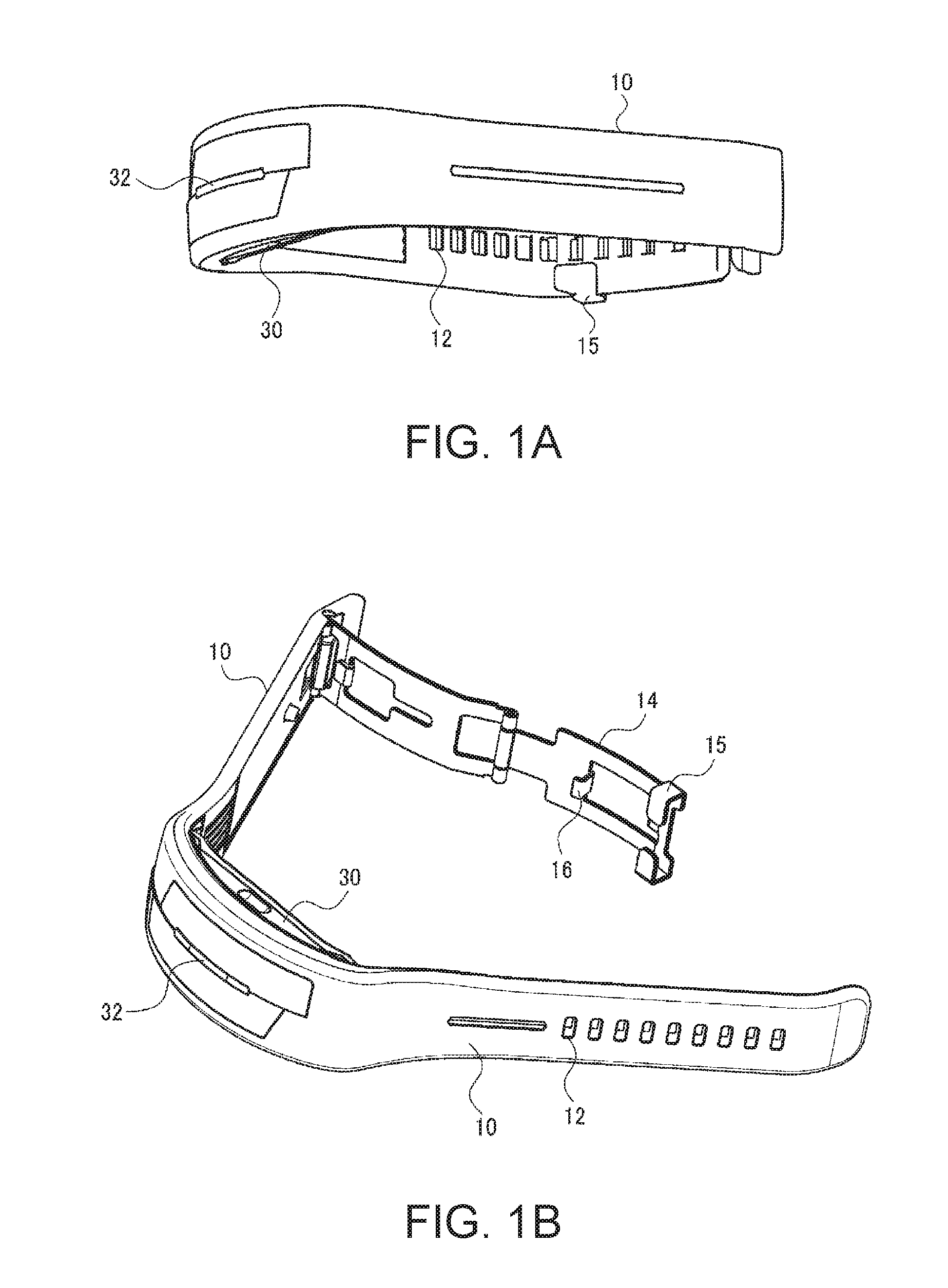
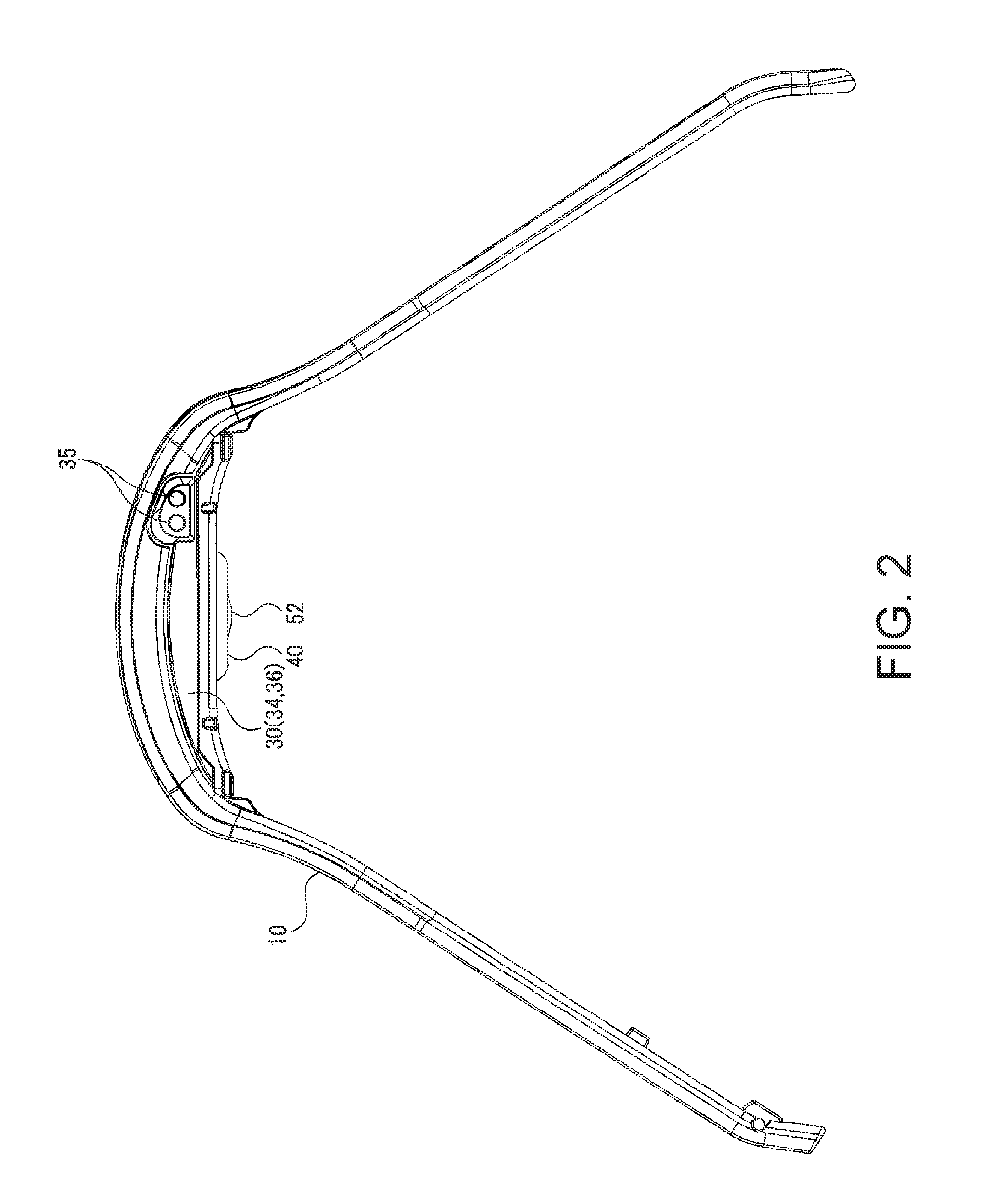
[0066]FIGS. 1A and 1B and FIG. 2 are schematic diagrams illustrating the exterior of a biological information measuring apparatus (biological information detecting apparatus) according to a first embodiment. FIG. 1A is a diagram when the biological information measuring apparatus is seen from the front, FIG. 1B is a diagram when the biological information measuring apparatus of FIG. 1A is obliquely seen from above, and FIG. 2 is a diagram when the biological information measuring apparatus is seen from the side.
[0067]As illustrated in FIGS. 1A and 1B and FIG. 2, the biological information measuring apparatus of this embodiment includes a band portion 10, a case portion 30, and a sensor unit 40 as a biological information measuring module. The case portion 30 is attached to the band portion 10. The sensor unit 40 is provided in the case portion 30. In addition, the biological information measuring apparatus...
modification example 1
of Arrangement
[0118]First, Modification Example 1 of the arrangement of a light emitting unit and a light receiving unit will be described with reference to FIG. 7. In the first embodiment described above, one light emitting unit 150 and one light receiving unit 140 are mounted on the substrate 160 (sensor substrate) so as to be lined up. In a configuration of Modification Example 1, a plurality of light emitting units and one light receiving unit are provided. A first light emitting unit 350 and a second light emitting unit 380 as a plurality of light emitting units, and a light receiving unit 340 are mounted on a substrate 360 so as to be lined up in a row along a predetermined direction in the order of the first light emitting unit 350, the light receiving unit 340, and the second light emitting unit 380. The first light emitting unit 350, the second light emitting unit 380, and the light receiving unit 340 are disposed so that a first interval D1 which is an interval between the...
modification example 2
of Arrangement
[0123]Next, Modification Example 2 of the arrangement of a light emitting unit and a light receiving unit will be described with reference to FIG. 8A. In a configuration of Modification Example 2, a first light emitting unit 450 and a second light emitting unit 480 as light emitting units, and a light receiving unit 440 are mounted on a substrate 460 so as to be lined up in a row along a predetermined direction in the order of the first light emitting unit 450, the light receiving unit 440, and the second light emitting unit 480. The first light emitting unit 450, the second light emitting unit 480, and the light receiving unit 440 are disposed so that a first interval D1 which is an interval between the first light emitting unit 450 and the light receiving unit 440 and a second interval D2 which is an interval between the second light emitting unit 480 and the light receiving unit 440 are set to be different distances. In addition, a light shielding member (light shie...
PUM
 Abstract
Description
Claims
Application Information
 - R&D
- Intellectual Property
- Life Sciences
- Materials
- Tech Scout
- Unparalleled Data Quality
- Higher Quality Content
- 60% Fewer Hallucinations
Browse by: Latest US Patents, China's latest patents, Technical Efficacy Thesaurus, Application Domain, Technology Topic, Popular Technical Reports.
© 2025 PatSnap. All rights reserved.Legal|Privacy policy|Modern Slavery Act Transparency Statement|Sitemap|About US| Contact US: help@patsnap.com


