Knife holder

a clamping and handle technology, applied in the field of clamping clamps, can solve the problems of end pieces threatening to be attached to the handle, and achieve the effects of firm and stable interface, enhanced interface, and enhanced safety

Inactive Publication Date: 2016-07-07
OUTDOOR EDGE CUTLERY CORP
View PDF5 Cites 3 Cited by
  • Summary
  • Abstract
  • Description
  • Claims
  • Application Information

AI Technical Summary

Benefits of technology

[0006]It is one aspect of embodiments of the present invention to provide a device that allows a knife to be converted into a harpoon for hunting and fishing. More specifically, a knife holder is provided that receives a knife. The contemplated knife holder has a groove, slot, or pocket that receives portions of the knife tang and pommel. The knife holder may have an elongated handle so the user can grip the knife away from the blade, which enhances safety. The knife holder groove dimensions may closely match the knife outer dimensions to provide a firm and stable interface between the knife and the knife holder. To further enhance the interface between the knife and the knife holder, some embodim...

Problems solved by technology

The end piece may be thre...

Method used


Image

  • Knife holder
  • Knife holder
  • Knife holder

Examples


Embodiment Construction

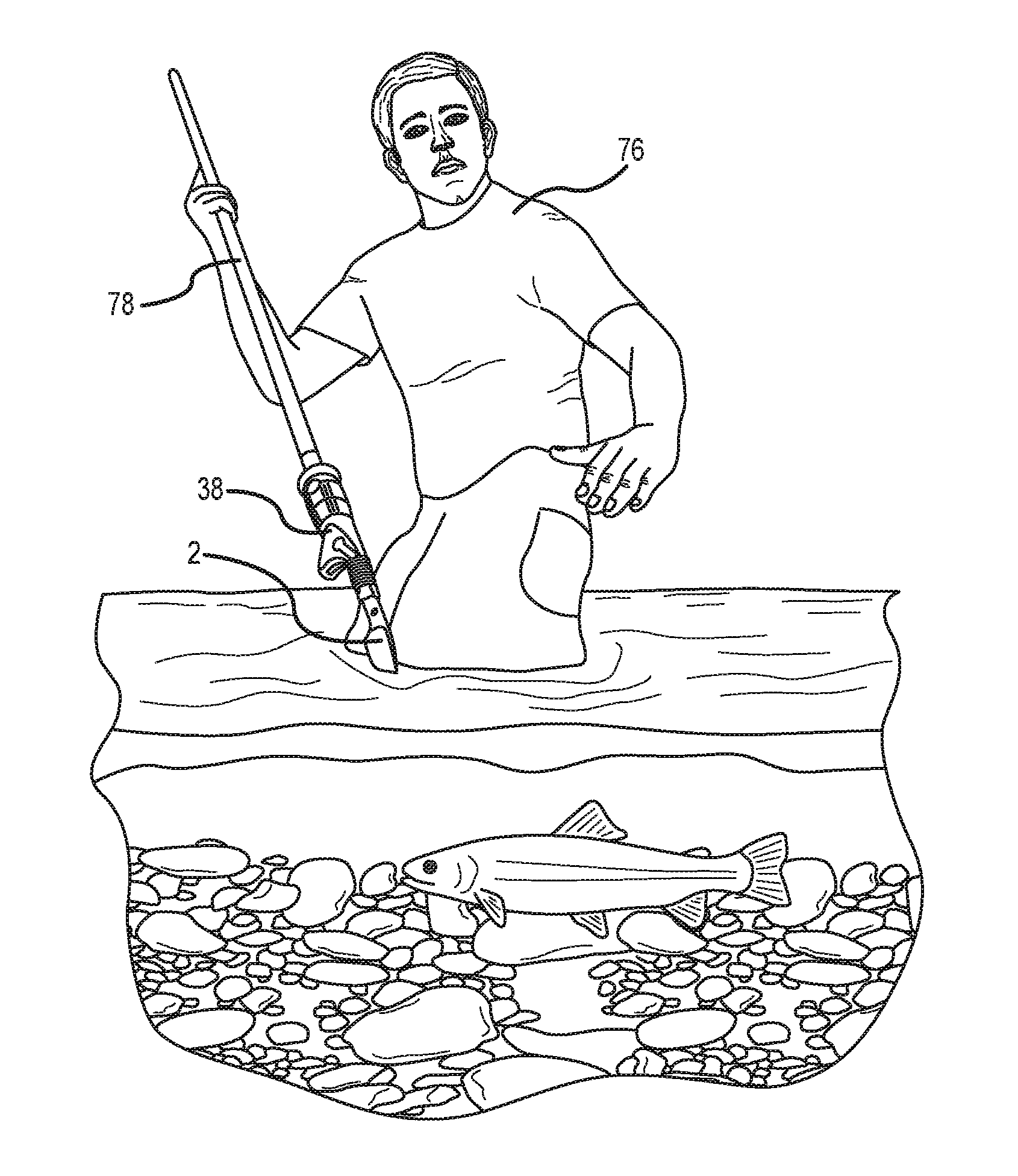
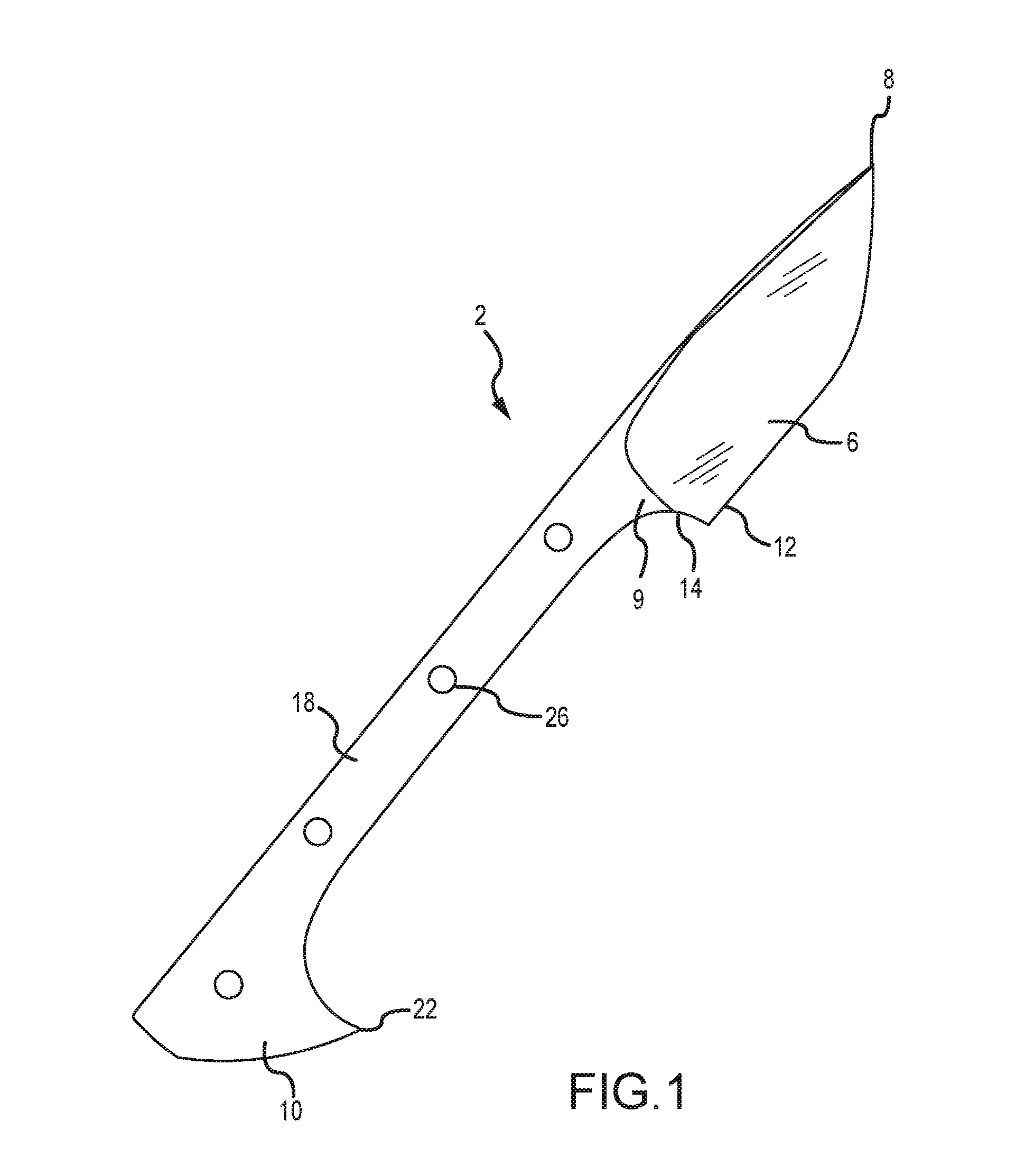
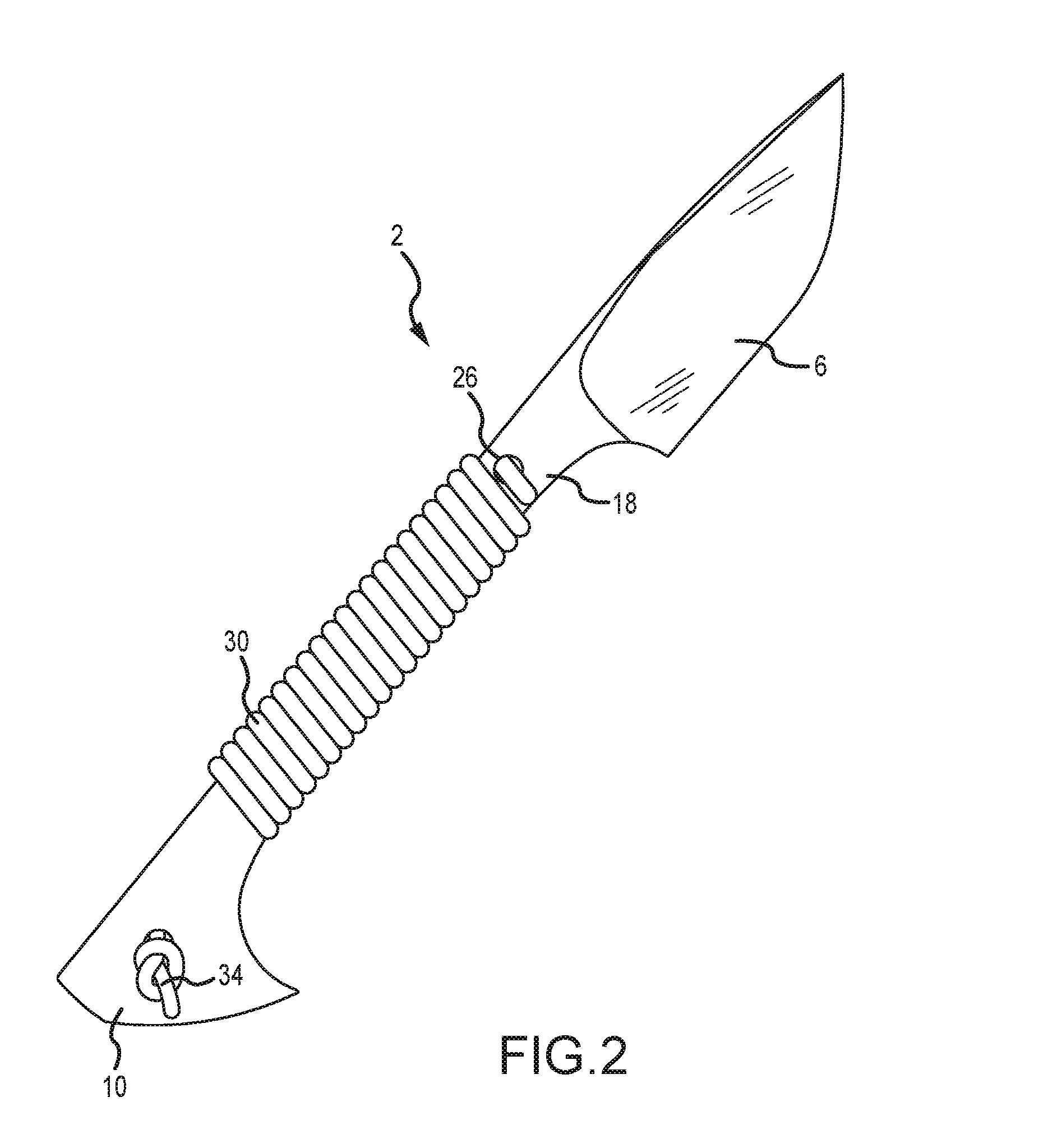
[0027]FIGS. 3-6 show a knife holder 38 for selectively receiving a knife 2 of one embodiment of the present invention. The knife holder 38 is designed to selectively interface with a tang and pommel of a knife (see FIGS. 1 and 2). The holder includes a groove 42 or slot for receipt of the knife 2. In one embodiment of the present invention, the dimensions of the groove 42 closely match corresponding portions of the knife 2. The knife holder 38 may include a plurality of holes 46 that correspond to holes 26 in the knife.

[0028]FIGS. 3 and 4 show the knife holder 38 of one embodiment of the present invention that includes the groove 42 that selectively receives a blade shown in FIG. 1. When the knife is installed, the holes 26 thereof are aligned with the holes 46 of the knife holder 38 as shown in FIG. 5. FIG. 6 shows the aligned holes that accept a cord 30 to fasten the knife 2 to the knife holder 38. Some embodiments of the present invention also include a lock 50 that selectively i...


PUM


Abstract

A knife holder is provided that is adapted to selectively receive a knife. The knife holder may include a lock, but the primary fastening mechanism between the knife and the knife holder is a cord. The knife holder may also have a handle with an open end for selective receipt of a branch, pole, or other similar device to convert the knife and knife holder into a harpoon.

Description

[0001]This application claims the benefit of U.S. Provisional Patent Application Ser. No. 62 / 099,350, filed Jan. 2, 2015, the entirety of which is incorporated by reference herein.FIELD OF THE INVENTION[0002]Embodiments of the present invention are generally related to a holder used to secure a knife. Some knife holders described herein can also receive a shaft to form a harpoon used by hunters and survivalists.BACKGROUND OF THE INVENTION[0003]FIGS. 1 and 2 show a knife 2 used by hunters and survivalists formed from a single piece of metal that includes a blade 6 at one end with a sharpened tip / point and a pommel 10 at an opposite end. The blade 6 has an edge 12 that may be straight, serrated, or combination thereof. The blade 6 ends at a heal 9 is adjacent to a finger guard 14. The finger guard leads to a tang 18 that connects the blade 6 to the pommel 10. The pommel 10 may have a shaped profile that terminates at a point 22 (e.g., a hawk's bill point). The tang 18 and pommel 10 ma...

Claims


Application Information

Patent Timeline
IPC IPC(8): B65D85/00B26B11/00A01K81/04B65D25/10B65D51/24B25G1/04B26B3/00
CPCB65D85/70B25G1/04B26B11/00A01K81/04B65D25/10B65D51/24B26B3/00B25G3/20
Inventor BLOCH, DAVID R.
Owner OUTDOOR EDGE CUTLERY CORP
Why Eureka
Try Eureka