A process for manufacturing an optical element by hot - forming a glass sheet

Inactive Publication Date: 2016-07-07
INST NAT DI ASTROFISICA INAF
View PDF27 Cites 3 Cited by
  • Summary
  • Abstract
  • Description
  • Claims
  • Application Information

AI Technical Summary

Benefits of technology

The present invention aims to provide a hot-forming process that is free from the problems of existing methods.

Problems solved by technology

For technological reasons, making such mirrors in one piece is unthinkable; each mirror is thus divided into a plurality of sectors.
The aforesaid known process has the drawback of an insufficient process repeatability introduced by the metal foil; indeed, the metal foil may display defects or form creases which translate into local deformations of the glass sheet.

Method used


Image

  • A process for manufacturing an optical element by hot - forming a glass sheet
  • A process for manufacturing an optical element by hot - forming a glass sheet
  • A process for manufacturing an optical element by hot - forming a glass sheet

Examples


Embodiment Construction

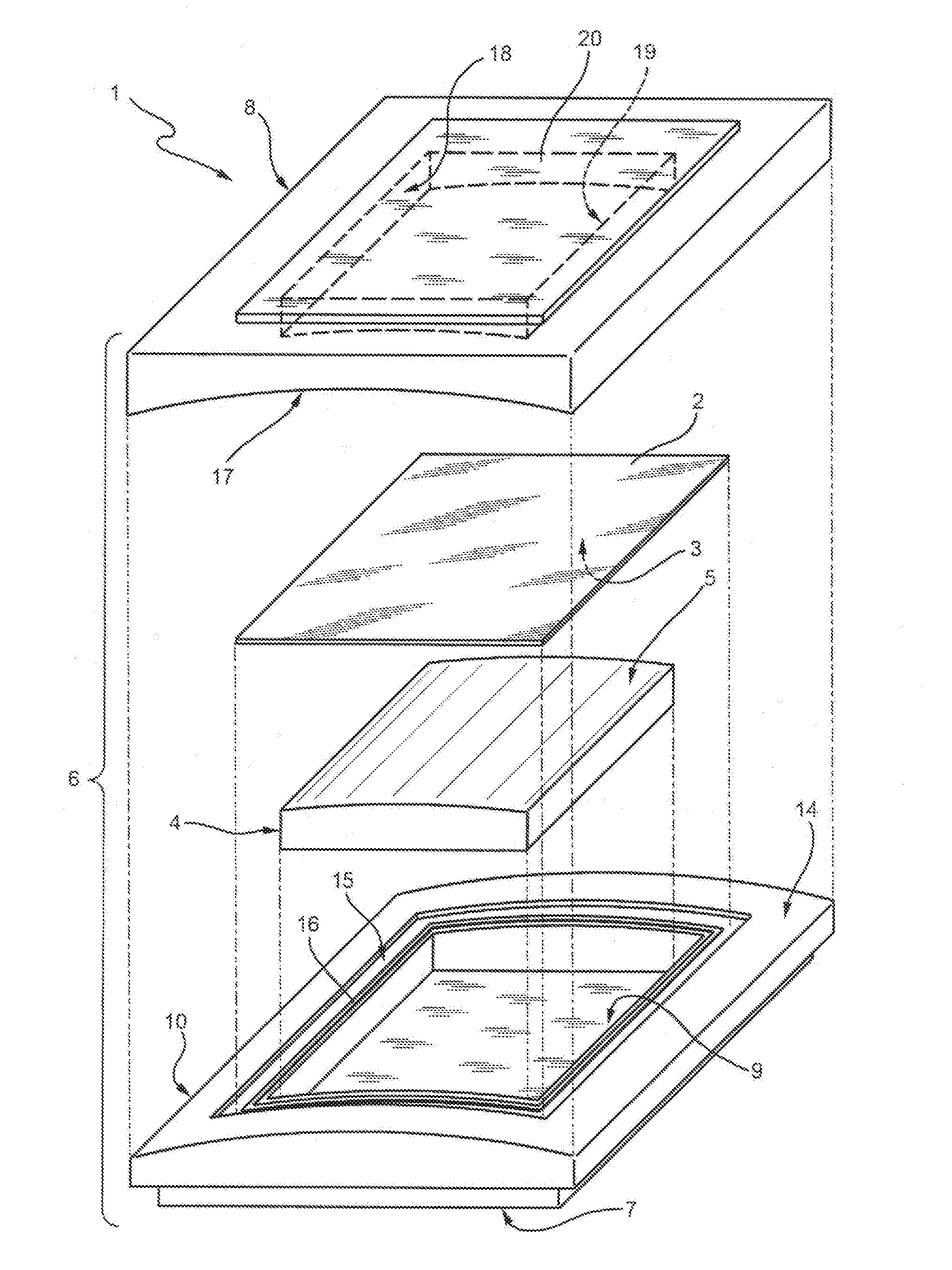
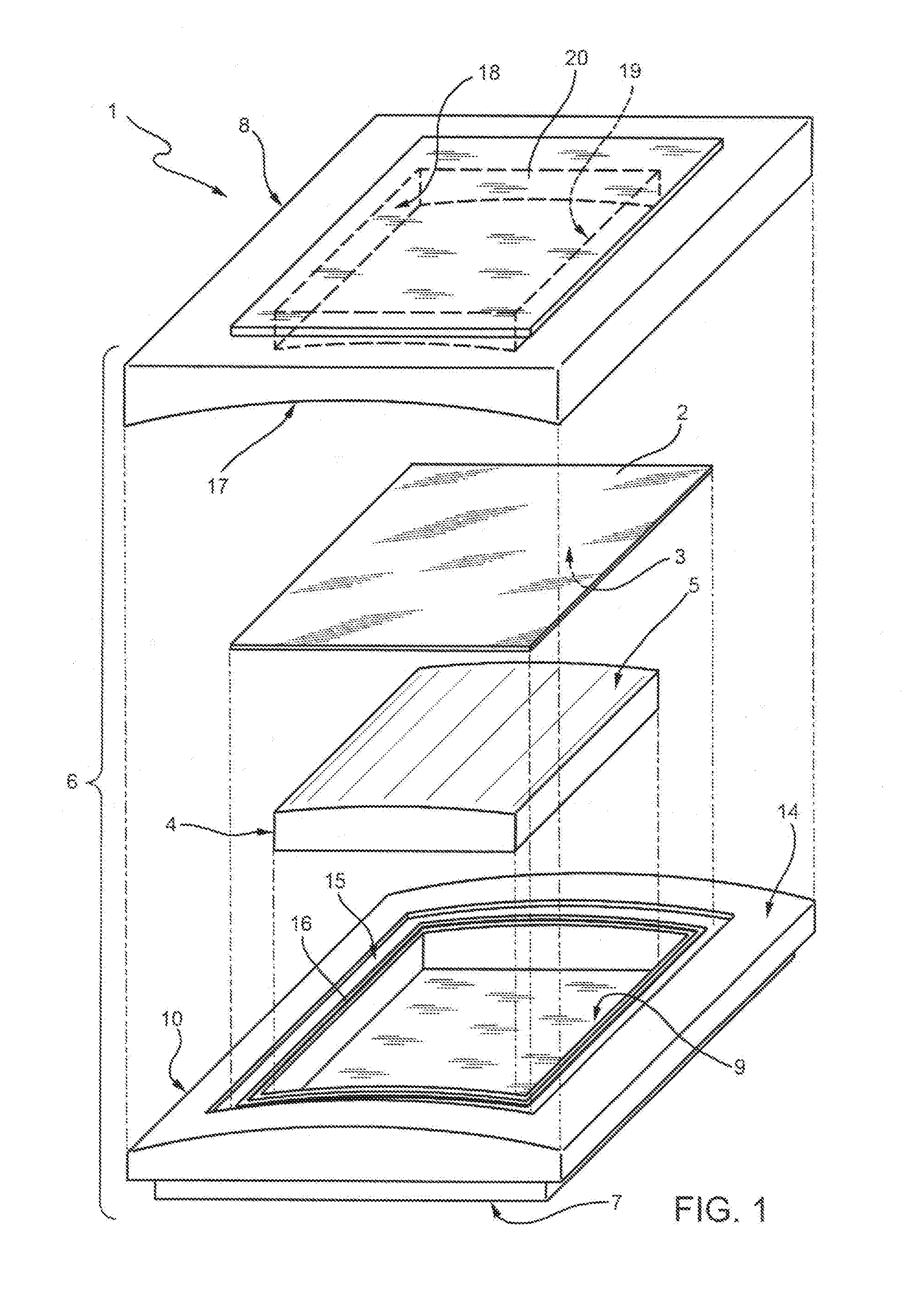
[0019]With reference to FIG. 1, reference numeral 1 is a device for implementing the hot-forming process of a glass sheet 2 according to the present invention.

[0020]The glass sheet 2 is a semi-finished starting product for making an aspherical (for example, parabolic) mirror sector for an X-ray grazing incidence telescope by means of the method of the invention.

[0021]For example, the size of the glass sheet 2 is 340×340 mm and the thickness is equal to 0.4 mm. Glasses which may be used for this purpose are, for example, D263 glass and AF32 glass made by SCHOTT AG. In FIG. 1, reference numeral 3 is the optical surface of the glass sheet 2, i.e. the face of the glass sheet adapted to form a portion sector of the optical surface of the mirror, in use.

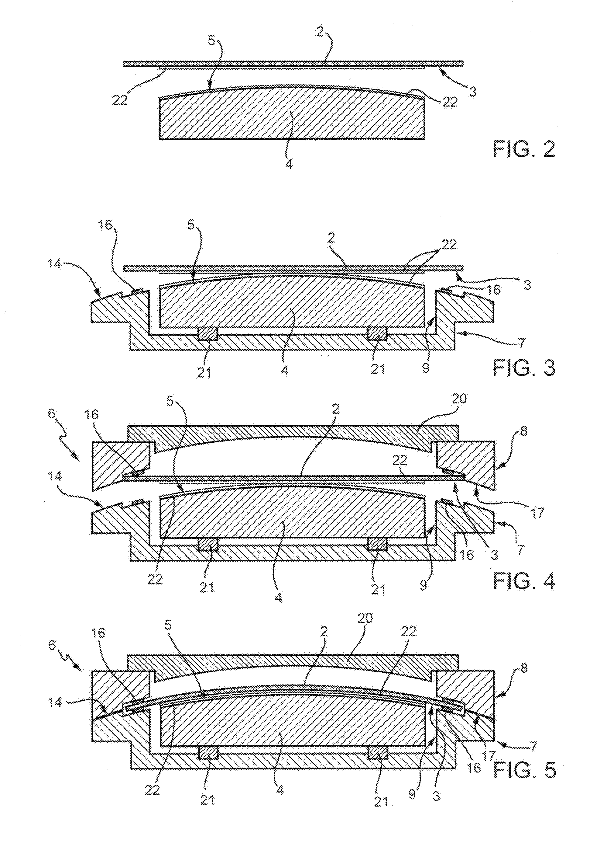
[0022]The device 1 comprises a mold 4 having an upper surface 5 which reproduces the shape to be given to the optical surface 3 of the glass sheet 2 by means of the process described below (direct slumping). It is worth noting that the pro...


PUM

PropertyMeasurementUnit
Timeaaaaaaaaaa
Fractionaaaaaaaaaa
Fractionaaaaaaaaaa

Abstract

A process for manufacturing an optical element by hot-forming a glass sheet (2), comprising the steps of:positioning a mold (4) in a cavity (9) of a base element (7) of a muffle (6);positioning the sheet (2) on the mold (4) with a peripheral edge superimposed on a closure area (14, 15) of the base element (7) surrounding the cavity (9);closing a cover (8) of the muffle (6) onto the base element (7), so as to maintain the peripheral edge of the glass sheet (2) in contact with the closure area (14, 15) of the base element (7); andperforming a controlled heating and cooling thermal cycle, by applying a pressure difference between the base element (7) and the cover (8) so as to press the glass sheet (2) onto the mold (4) after reaching the maximum temperature.

Description

TECHNICAL FIELD[0001]The present invention relates to a process for manufacturing an optical element by hot-forming a glass sheet.BACKGROUND ART[0002]The preferred, yet not exclusive application of the invention is in the making of thin optical elements, such as, for example, adaptive optics or X-ray mirrors: without losing in generality, reference will be made hereinafter to X-ray grazing incidence optics for telescopes.[0003]In order to improve (decrease) the weight / effective area ratio of the grazing incidence optics, the use of glass is taken into consideration because it allows to consider X-ray telescopes of increasingly larger size, for example with an effective area in the order of a few square meters, while maintaining the weight of the system within the limits set by the current rockets for launching into orbit (the systems may only operate from space, given the opacity of the Earth's atmosphere to the considered X-ray wavelengths). Effective areas in the order of 3-4 m2 a...

Claims


Application Information

Patent Timeline
IPC IPC(8): C03B40/00C03B23/035
CPCC03B23/0357C03B40/005C03B23/0355C03C2218/355
Inventor GHIGO, MAUROPROSERPIO, LAURA
Owner INST NAT DI ASTROFISICA INAF
Why Eureka
Try Eureka