
Method for determining aircraft center of gravity independent of measuring aircraft total weight

a technology of aircraft center and total weight, which is applied in the direction of instruments, electric/magnetic computing, analogue processes for specific applications, etc., can solve the problems of aircraft aerodynamic drag, fuel is the most expensive item in an airline's annual expenses, and the airline's profit margin is slim

Inactive Publication Date: 2016-07-07
NANCE C KIRK
View PDF0 Cites 18 Cited by
  • Summary
  • Abstract
  • Description
  • Claims
  • Application Information

AI Technical Summary

Benefits of technology

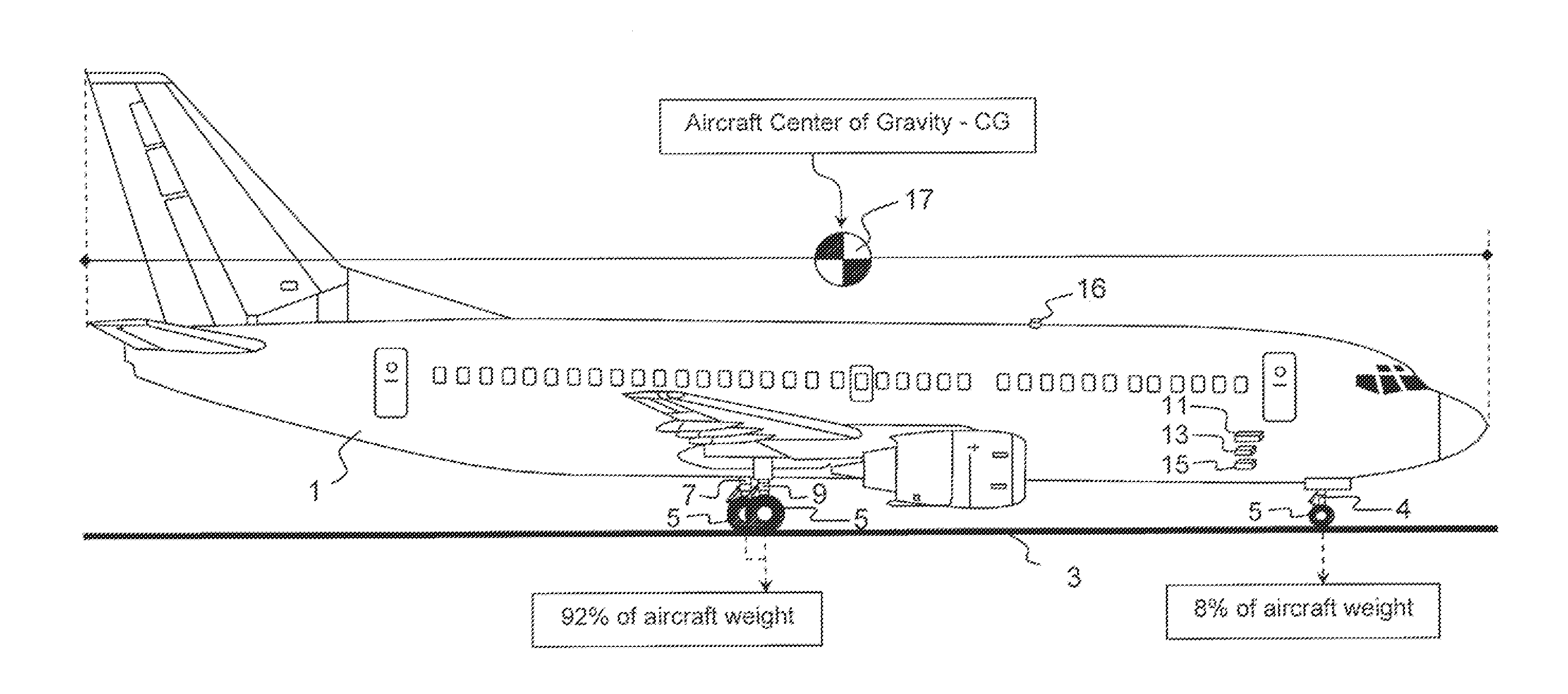
The present invention provides a method for determining the Center of Gravity of an aircraft on the ground without the need to measure the weight of the aircraft. This is done by measuring the weight supported by the main and nose landing gear struts and using a load build-up process to determine the total weight of the aircraft. The method can also include measuring the internal pressure of the nose landing gear strut and the rotation of a linkage on the nose landing gear strut. The Center of Gravity can be determined as a percentage of the distance between the nose and the main landing gear struts or as a distance measured from an aircraft datum line. The method can be used to determine the Center of Gravity for an aircraft under regulation by the Regulatory Authority.

Problems solved by technology

If the aircraft CG is too far aft and outside the aircraft's certified CG limits, the aircraft nose can rise uncontrollably during take-off, where the aircraft will become unstable, resulting in a stall and possible crash.
Furthermore, fuel is the most costly item in an airline's annual expenses.
Airline profit margins are slim at best, so any and all efforts must be used to reduce fuel consumption.
This additional rear stabilizer trim will increase the aerodynamic drag on the aircraft, thus consume more fuel.
Aircraft brake wear and tire wear result in a minimal and virtually insignificant amount of weight loss to the unsprung weight.
Among the disadvantages of the prior art onboard aircraft weight measuring systems are that airlines can suffer severe schedule disruptions by using a “measured” aircraft weight value, as opposed to methods of “calculating” aircraft weight based upon the LBUM.
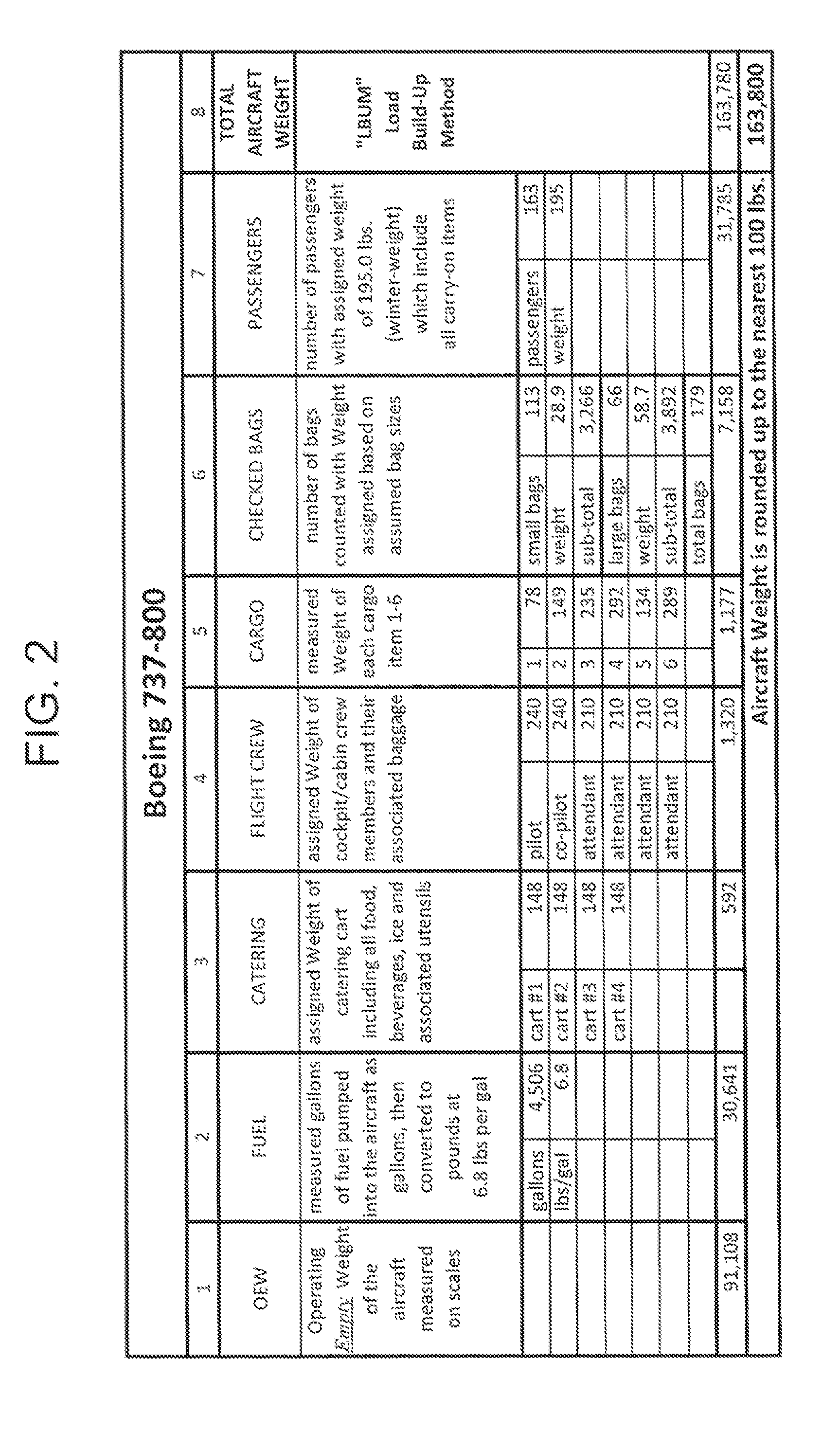
Aircraft have a Maximum design Take-Off Weight “MTOW” limitation, where airline operations use assumptions as to the weight of passengers and baggage loaded onto the aircraft, to stay below the aircraft MTOW limitation.
Using a means to measure the actual aircraft weight, just as the aircraft door closes, and the possibility of the measured weight not matching the calculated weight of the LBUM, would have the airline facing a potential departure delay to resolve any difference in the two separate but parallel weight determinations.
This potential for delay in the flight departure, on as many as 2,200 daily flights for a single airline, results in the various airlines not willing to take the risk of hundreds of flight delays each day.
This creates an incentive for airlines to continue to use the FAA approved assumed weights, irregardless to whether the assumed aircraft weight determination is accurate.
The FAA has expressed concerns regarding any airline which might measure total aircraft weight, but chose to not disclose such measured total aircraft weight on the aircraft flight manifest.
Airlines would appreciate an opportunity to use the CG tracking capabilities of today's aircraft weight and balance systems, to more efficiently place baggage and cargo below decks, and take advantage of the reduced fuel consumption benefits; but are not willing to take the risk of scheduled departure delays when the aircraft's planned weight as determined by weight assumptions does not match an actual measured total aircraft weight.

Method used


Image

  • Method for determining aircraft center of gravity independent of measuring aircraft total weight
  • Method for determining aircraft center of gravity independent of measuring aircraft total weight
  • Method for determining aircraft center of gravity independent of measuring aircraft total weight

Examples


Embodiment Construction

[0045]An aircraft is typically supported by plural landing gear struts. In many if not most cases, the aircraft is supported by three landing gear struts. Each landing gear strut is designed much like and incorporates many of the features of a telescopic shock absorber. The shock absorber of the landing gear strut comprises internal fluids of both hydraulic oil and compressed nitrogen gas. More simply said the weight of an aircraft rests on three pockets of compressed nitrogen gas. Pressure contained within the landing gear struts is measured in “psi”. With any object that has a “known total weight” which is resting on three independent points, and one of the three points has a measured weight, the combined weight supported by the remaining two points can be determined by subtracting the one measured weight from the known total weight.

[0046]The present invention offers a new method to determine aircraft CG. Total aircraft weight is determined independently of measuring the weight su...


PUM


Abstract

A method for determining a Center of Gravity of an aircraft, which is independent of measuring the aircraft weight. The total aircraft weight is determined by a method independent of measuring the weight supported by the main landing gear struts. The weight supported by the nose landing gear strut is subsequently measured. The measured weight associated with nose landing gear is subtracted from the independently determined total aircraft weight, to determine a calculated weight supported by the combined main landing gear struts. The resulting determined weight supported by the combined main landing gear is compared to the independently determined total aircraft weight, and allows for determination of the aircraft Center of Gravity. Inversely the measured nose strut weight is compared to the total aircraft weight, and allows for determination of the aircraft Center of Gravity. Aircraft Center of Gravity is determined without the total aircraft weight being measured.

Description

BACKGROUND OF THE INVENTION[0001]There are many critical aspects of an aircraft taking flight, which a commercial airline must resolve when determining if a departing aircraft is safe for take-off. Two of these factors are identifying the proper Weight and Center of Gravity for the aircraft. Hereinafter, aircraft “Center of Gravity” will be referred to as aircraft “CG.”[0002]The Federal Aviation Administration (“FAA”) has published FAA-Advisory Circular AC20-161 defining requirements for onboard aircraft weight and balance systems used to “measure” the aircraft weight. Variations of onboard aircraft weighing systems basically convert the aircraft landing gear struts into scales. Prior art methods for converting aircraft landing gear struts into scales are well documented and reference may be made to United States patents: #3,513,300 - Elfenbein#5,548,517 - Nance#3,584,503 - Senour #6,128,951 - Nance#3,701,279 - Harris  #6,237,406 - Nance#5,214,586 - Nance  #6,237,407 - Nance#5,521,8...

Claims


Application Information

Patent Timeline
Patent Type & Authority Applications(United States)
IPC IPC(8): G01M1/12G01G19/07B64D45/00
CPCG01M1/125G01G19/07B64D45/00B64D9/00
Inventor NANCE, C. KIRK
Owner NANCE C KIRK
Learn More