
On-board device for measuring the mass and the position of the center of gravity of an aircraft

a technology for aircraft and on-board devices, which is applied in the direction of aircraft floors, analog and hybrid computing, complex mathematical operations, etc., can solve the problems of difficult implementation, difficult to perform, and difficulty in applying the third devi

Active Publication Date: 2013-03-19
EUROCOPTER
View PDF11 Cites 7 Cited by
  • Summary
  • Abstract
  • Description
  • Claims
  • Application Information

AI Technical Summary

Benefits of technology

The use of an eddy current sensor has several benefits. Firstly, it is not affected by temperature, which means it can be used in different climate conditions. Additionally, it can be easily attached to existing deformable elements without requiring major modifications.

Problems solved by technology

Since measuring empty mass in this way is very difficult to perform, it is not performed prior to each flight, given the equipment and the time required, which is highly penalizing for that first device, particularly in terms of precision.
Although that second device works, it nevertheless presents various drawbacks, in particular associated with strain gauges since they:are difficult to put into place;are sensitive to temperature, which requires the use of means specifically for temperature compensation; andthey need to be recalibrated frequently.
Nevertheless, experience shows that arranging two inclinometers on each landing gear presents major difficulties that lead to difficulties in applying that third device.

Method used


Image

  • On-board device for measuring the mass and the position of the center of gravity of an aircraft
  • On-board device for measuring the mass and the position of the center of gravity of an aircraft
  • On-board device for measuring the mass and the position of the center of gravity of an aircraft

Examples


first embodiment

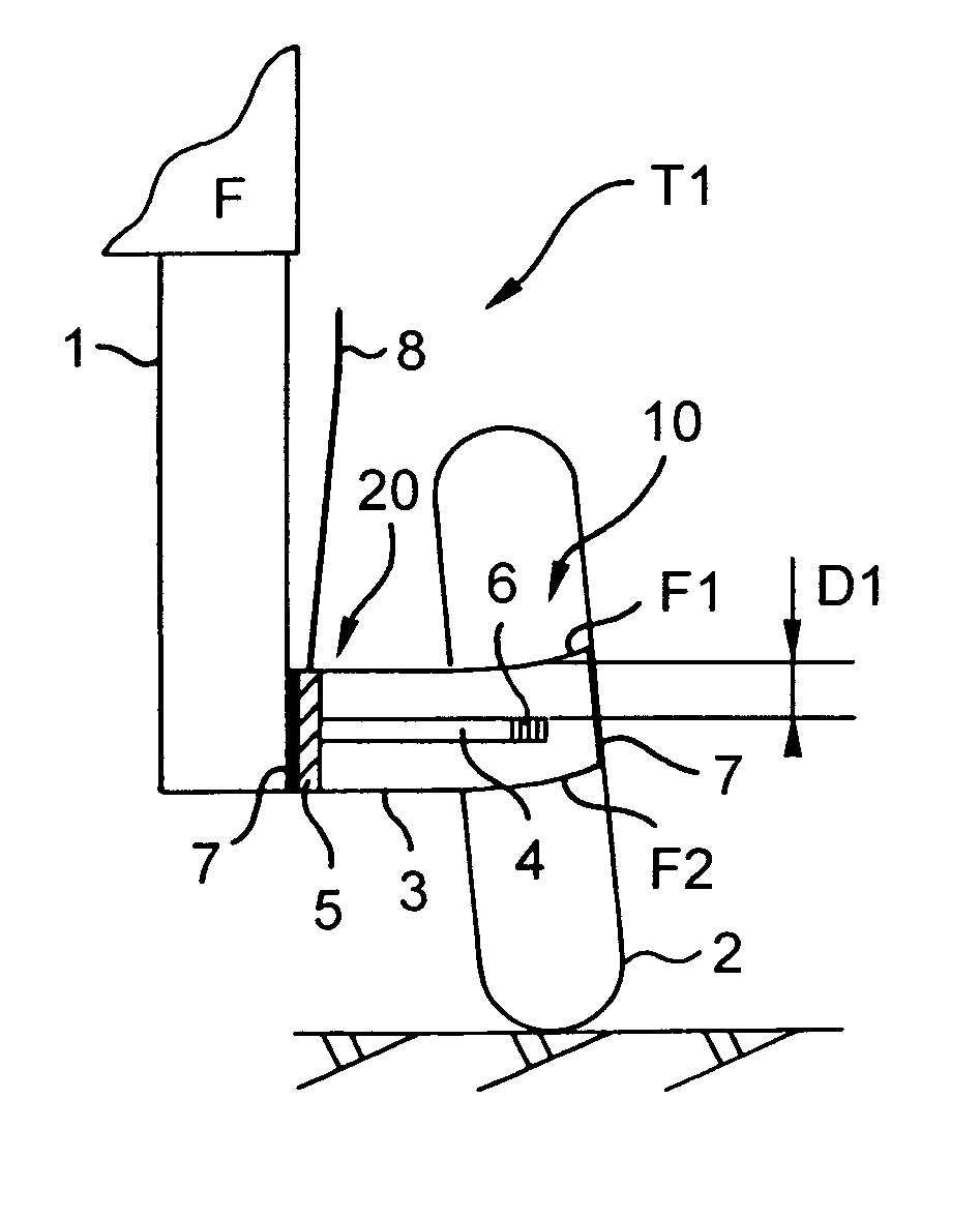
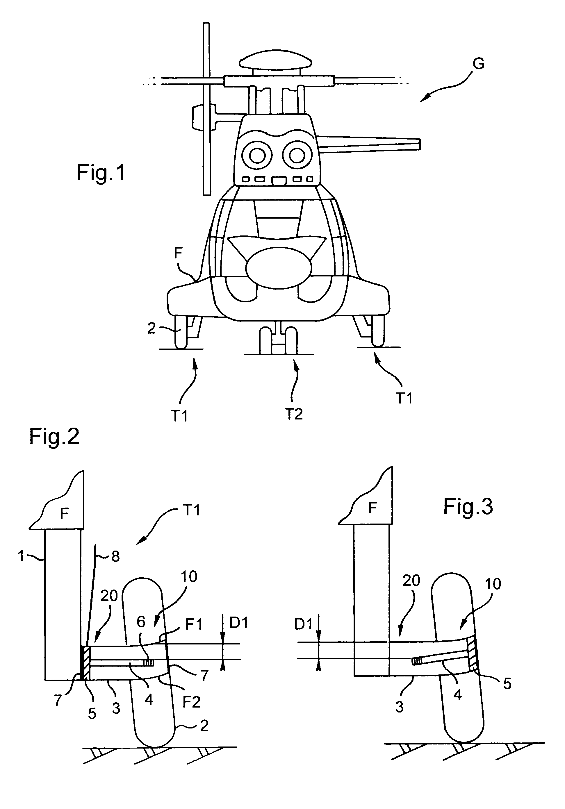
[0034]FIG. 2 shows how a bar provided with an eddy current sensor is arranged inside a deformable element.

[0035]The landing gear T1 is of the wheeled type. The first and second ends 10 and 20 of a deformable element 3 are secured respectively to a wheel 2 and to a connection member 1, e.g. a damper, connected to the fuselage F. Under the action of the mass of the aircraft, the first end 10 of the deformable element is deformed.

[0036]A bar 4 is inserted inside the deformable element 3 and is then fastened thereto by conventional fastener means 5. In this embodiment, the fastener means 5 is situated at the second end 20 of the deformable element 3. Thus, the bar 4 does not move regardless of the mass of the aircraft, and consequently regardless of the resulting force, i.e. the weight of the aircraft.

[0037]Once the bar 4 is in position, the first and second ends 10 and 20 are closed using seals 7 so as to avoid deposits intruding, that might otherwise interfere with measurement.

[0038]I...

second embodiment

[0041]With reference to FIG. 3, in a second embodiment, the fastener means 5 is no longer fastened to the second end 20 of the deformable element 3, but instead to its first end 10. In this configuration, the bar 4 is movable. Under the effect of the weight of the aircraft, the first end 10 deforms, thereby tilting the fastener means 5 a little and consequently tilting the bar 4. The distance D1 measured by the eddy current sensor is thus increased.

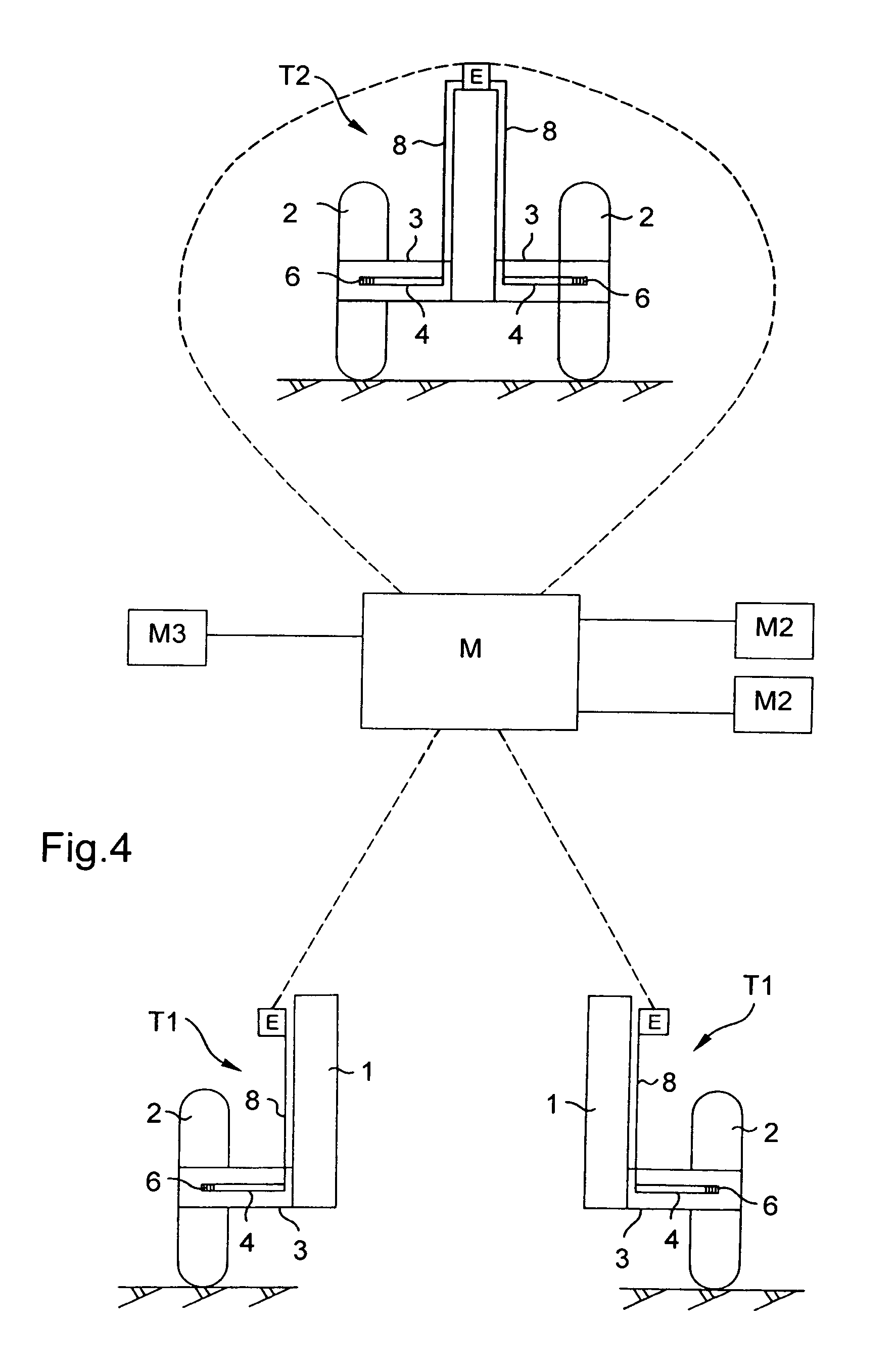
[0042]As described above, in a first variant of the first and second embodiments of the invention, the cable 8 is connected directly to the processor means and to the electrical power supply.

[0043]Nevertheless, in a second variant, the cable 8 is connected to a wireless transceiver, of the very high frequency type for example, arranged on the landing gear.

[0044]This transceiver feeds electricity to the sensor 6 and transmits the main signal to the processor means. It serves firstly to reduce the amount of cabling, and secondly to avoid po...


PUM


Abstract

The present invention relates to an on-board device for measuring the mass and the position of the center of gravity of an aircraft having a plurality of landing gears (T1, T2), each landing gear (T1, T2) being provided with at least one contact member (2) having a deformable element (3) that is deformable under the action of the weight of the aircraft when the aircraft is standing on a surface, and is remarkable in that the formable element (3) is provided with a bar (4) having an eddy current sensor (6) at its free end.

Description

[0001]The present invention relates to an on-board device for measuring the mass and the position of the center of gravity of an aircraft, e.g. a rotorcraft.BACKGROUND OF THE INVENTION[0002]It is known that these two items of information are critical factors in the safe and effective operation of any aircraft. Prior to each flight, the pilot of a vehicle of this type must therefore make sure that the mass and the balancing of the aircraft do not exceed limits that are predefined by the manufacturer.[0003]A first device is known, that is not on-board the aircraft itself, that serves to weigh an aircraft when empty, i.e. without any loading (passengers, fuel, . . . ), by arranging the aircraft under very precise conditions on a plurality of actuators, themselves disposed on special plates for avoiding introducing interfering forces. The empty mass is then added to the mass of the load in order to estimate the total mass of the aircraft before take-off and the position of its center of...

Claims


Application Information

Patent Timeline
Patent Type & Authority Patents(United States)
IPC IPC(8): B64C1/22
CPCG01G19/07G01G23/3728
Inventor LEROY, JULIETARDY, BERTRAND
Owner EUROCOPTER
Learn More