Extraocular epiretinal implant

a technology of epiretinal implants and implants, which is applied in the field of extraocular epiretinal implants and visual prostheses, can solve the problems of large space requirements, partial or full loss of eyesight, and known visual prostheses

a technology of epiretinal implants and implants, which is applied in the field of extraocular epiretinal implants and visual prostheses, can solve the problems of large space requirements, partial or full loss of eyesight, and known visual prostheses

US20160199650A1Active Publication Date: 2016-07-14PIXIUM VISION SA

Image

  • Extraocular epiretinal implant
  • Extraocular epiretinal implant
  • Extraocular epiretinal implant

Examples


third embodiment

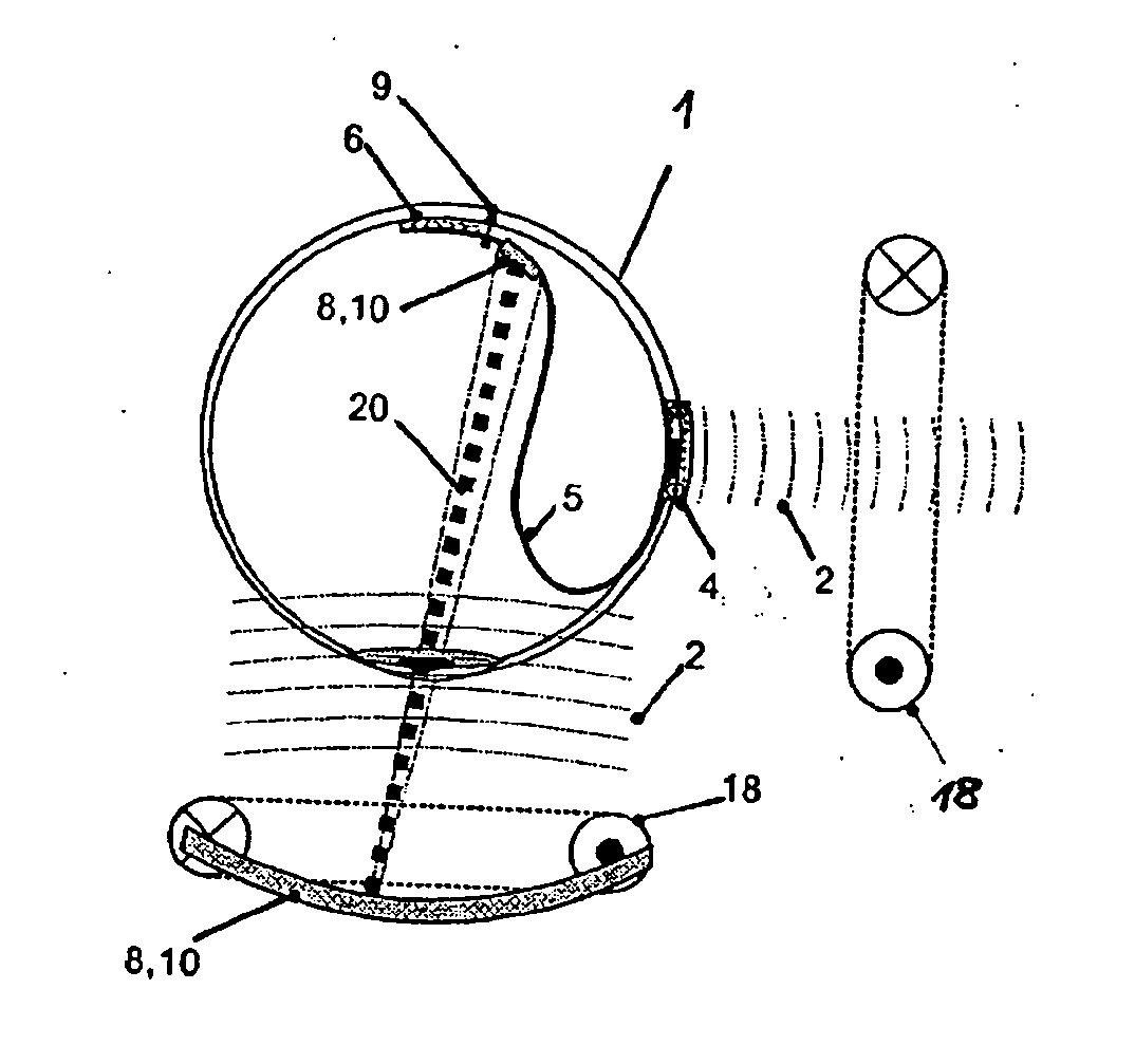
[0157]In contrast to the visual prosthesis represented in FIG. 3, in the third embodiment shown in FIG. 4 arranged on the right-hand side of the eye there is a transmitter coil 18 which lies outside the body and transfers signals inductively to the intracorporeal transmitter / receiver coil 4 via electromagnetic waves 2. The signals received by the intracorporeal transmitter / receiver coil 4 are then forwarded via the wire connection 5 to the intraocular part of the visual prosthesis.

[0158]Arranged below the eye 1, there is a receiver coil 18 which also lies outside the body and inductively receives the electromagnetic signals 2 emitted by the extraocular transmitter / receiver coil 4. In this way, signals or data can be transferred inductively from outside the eye 1 to the intraocular part of the visual prosthesis and, in the other direction, signals or data can be transmitted inductively in parallel operation from inside the eye 1 to the extracorporeal part of the visual prosthesis, as...

fifth embodiment

[0165]Arranged on the right hand side of the eye 1, there is a transmitter / receiver coil 18 which lies outside the body and, via electromagnetic waves 2, transfers signals inductively to the transmitter / receiver coil 4, which are forwarded from the extraocular part via the wire connection 5 to the intraocular part of the visual prosthesis. Similarly as in the embodiments represented in FIG. 5, a separate receiver coil is likewise not provided in this fifth embodiment, but the extracorporeal transmitter / receiver coil 18 can both transmit and receive electromagnetic. waves 2 like the intracorporeal transmitter / receiver coil 4. Via this bidirectional interface between the transmitter / receiver coil 4 and the transmitter / receiver coil 18, signals or data can be transferred inductively from outside the eye 1 to the intraocular part of the visual prosthesis and, in the other direction, signals or data can be transmitted inductively in an alternating operation mode from inside the eye 1 to ...


PUM


Abstract

A visual prosthesis in the form of a retinal implant, which is distinguished by the least possible space requirement inside the eye, is achieved by a visual prosthesis having an intraocular implant and an extraocular implant, which supplies the intraocular implant with energy and controls it. Virtually all the electronic components, which do not necessarily need to be accommodated with the intraocular implant inside the eye, can be arranged outside the eyeball, for example on the sclera. In this way, the space requirement of the stimulation system inside the eye is reduced and the operative intervention for implanting the stimulation system inside the eye is kept as small as possible. A bidirectional inductive interface between an extracorporeal part of the visual prosthesis and an intracorporeal part, including the intraocular and extraocular implants, via which a current supply and bidirectional data transmission can be carried out is provided.

Description

CROSS REFERENCE TO RELATED APPLICATIONS[0001]This application is a Continuation application of U.S. patent application Ser. No. 11 / 988,634, filed Jun. 23, 2009, now, U.S. Pat. No. 9,289,325, which is a U.S. national stage application of PCT / EP2006 / 005273, Published as WO 2007 / 006376, filed Jun. 2, 2006, which claims priority to German patent Application Number 10 2005 032 989.6, filed Jul. 14, 2005, herein incorporated by reference in their entireties.BACKGROUND OF THE INVENTION[0002]The present invention relates to a device for implantation in a human eye, having an electrode array or a microcontact structure for contacting nerve tissue in the visual system of the human eye. The present invention relates in particular to a visual prosthesis having a device for generating stimulation impulses, which are used to stimulate living tissue or nerves.[0003]One frequent cause of the partial or full loss of eyesight is destruction of the photoreceptor layer in the retina of the human eye, a...

Claims


Application Information

Patent Timeline
14 Jul 2016
Publication
US20160199650A1
IPC
A61N1/36; A61N1/372; A61N1/05
CPC
A61N1/36046; A61N1/37223; A61N1/0543; A61F9/08; A61N1/025; A61N1/37229; A61N1/3787; G02B27/017
Inventors
ZEHNDER, THOMAS; TIEDTKE, HANS-JURGEN