
Downhole gas compression separator assembly

a separator and gas compression technology, applied in the direction of fluid removal, earth-moving drilling, borehole/well accessories, etc., can solve the problems of preventing the intake of production fluid and the inability to produce natural gas from wells

Inactive Publication Date: 2016-07-14
HALLIBURTON ENERGY SERVICES INC
View PDF4 Cites 34 Cited by
  • Summary
  • Abstract
  • Description
  • Claims
  • Application Information

AI Technical Summary

Benefits of technology

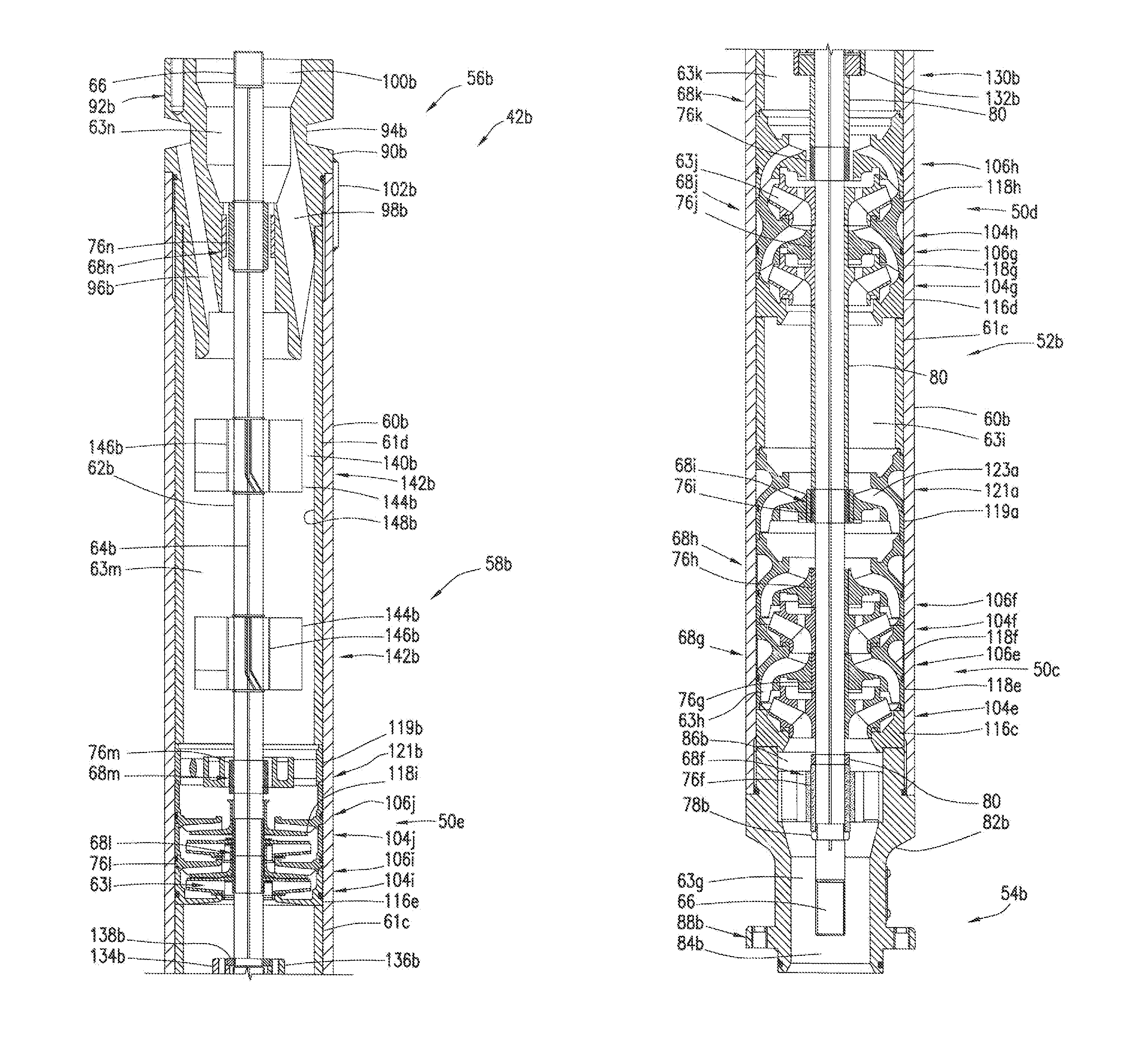
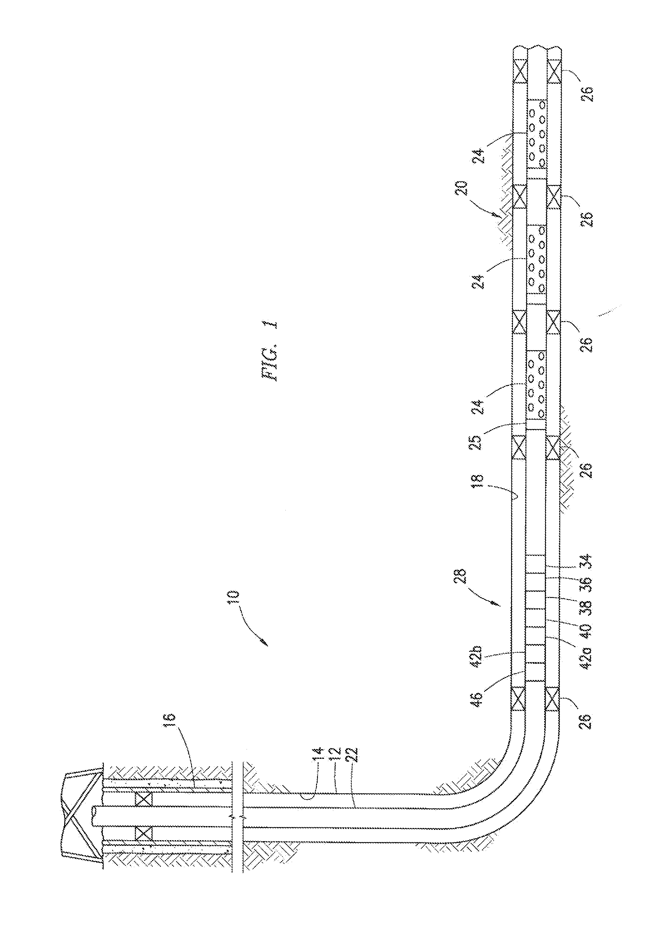
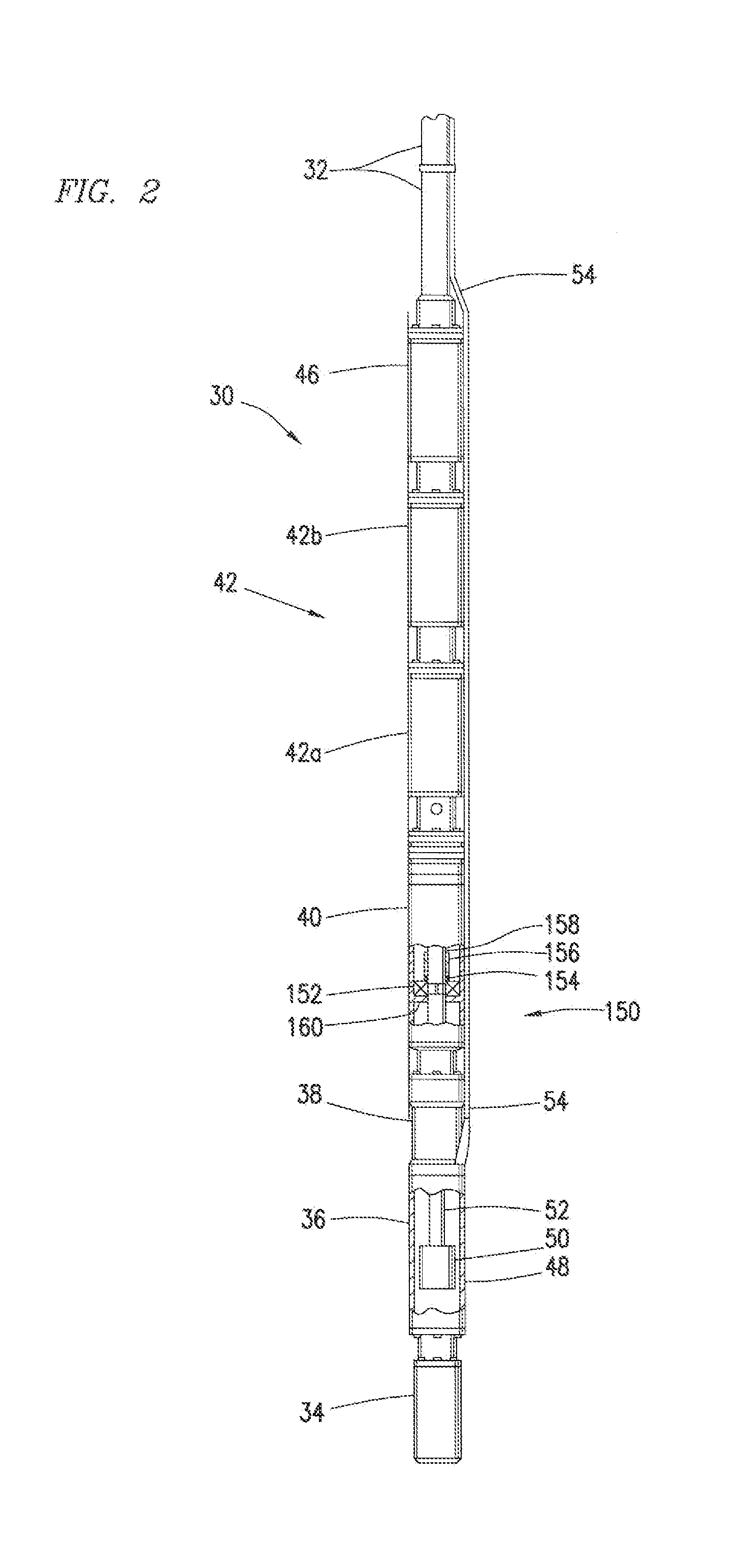
The patent text describes an apparatus and method for reducing free gas in production fluid from a wellbore extending through a subterranean reservoir. The invention addresses the problem of gas lock, which occurs when gas is present in the production fluid and interferes with the operation of the pump. The invention uses a gas compression separator assembly to separate the gas from the liquid fluid and compress it to dissolve or entrain the gas. The invention also includes various tools and equipment used in the well system, such as an electrical submersible pump, power cable, and downhole tools. The technical effects of the invention include reducing gas lock, improving pump efficiency, and reducing the amount of gas produced from wells with both gas and oil.

Problems solved by technology

The presence of compressible gas, or free gas, interferes with operation of the pump, preventing intake of production fluid.
Further, it is often undesirable to produce natural gas from wells having both gas and oil, for example.

Method used


Image

  • Downhole gas compression separator assembly
  • Downhole gas compression separator assembly
  • Downhole gas compression separator assembly

Examples


Embodiment Construction

[0013]While the making and using of various embodiments of the present disclosure are discussed below, a practitioner of the art will appreciate that the disclosure provides concepts which can be applied in a variety of specific embodiments and contexts. The specific embodiments discussed herein are illustrative of specific ways to make and use the disclosed apparatus and methods and do not limit the scope of the claimed invention.

[0014]As used herein, the words “comprise,”“have,”“include,” and all grammatical variations thereof are each intended to have an open, non-limiting meaning that does not exclude additional elements or steps. It should be understood that, as used herein, “first,”“second,”“third,” etc., are arbitrarily assigned, merely differentiate between two or more items, and do not indicate sequence. Furthermore, the use of the term “first” does not require a “second,” etc.

[0015]The terms “uphole” and “downhole,”“upward” and “downward,” and the like, refer to movement o...


PUM


Abstract

Downhole Electric Submersible Pumps (ESP) in a production string often experience gas lock caused by free gas present in the production liquids which reduces intake pressure below the operating parameters of the ESP. A gas compression separator assembly, having a series of compressors and separation chambers, entrains or dissolves the free gas component of the production fluid and separates free gas for downhole disposal. The production fluid fed to the ESP intake has an increased fluid pressure, a reduced volumetric fluid flow, and a lower free gas content, and is less likely to induce gas lock of the ESP.

Description

CROSS-REFERENCE TO RELATED APPLICATIONS[0001]None.FIELD OF INVENTION[0002]The disclosure generally relates to production of hydrocarbon-bearing fluids from a wellbore extending through a subterranean reservoir. More particularly, the disclosure addresses apparatus and methods for reducing free gas in production fluid by separating free gas from production liquid and by compressing the production fluid to dissolve or entrain free gas.BACKGROUND OF INVENTION[0003]In the production of hydrocarbons from a wellbore extending through a hydrocarbon-bearing zone in a reservoir, a production string or tubing is often positioned in the wellbore. A production string can include multiple downhole tools, pipe sections and joints, sand screens, flow and inflow control devices, etc. To pump production fluid to the surface, an electrical submersible pump (ESP), powered by an electric motor through a drive shaft, is positioned downhole in the wellbore. Electrical power is typically provided from a s...

Claims


Application Information

Patent Timeline
Patent Type & Authority Applications(United States)
IPC IPC(8): E21B43/38E21B43/12
CPCE21B43/128E21B43/38
Inventor HARDEE, JIM D.PARKS, KENNETH W.
Owner HALLIBURTON ENERGY SERVICES INC
Learn More