High reliability robotic cross-connect systems

a robotic cross-connect system, high-reliability technology, applied in the direction of manipulators, gripping heads, instruments, etc., can solve the problems of unsuitable large-scale production networks, achieve high length efficiency, improve quality, and minimize transverse compliance

a robotic cross-connect system, high-reliability technology, applied in the direction of manipulators, gripping heads, instruments, etc., can solve the problems of unsuitable large-scale production networks, achieve high length efficiency, improve quality, and minimize transverse compliance

US20160202424A1Active Publication Date: 2016-07-14TELESCENT

Image

  • High reliability robotic cross-connect systems
  • High reliability robotic cross-connect systems
  • High reliability robotic cross-connect systems

Examples


Embodiment Construction

I. Robotic Cross-Connect System

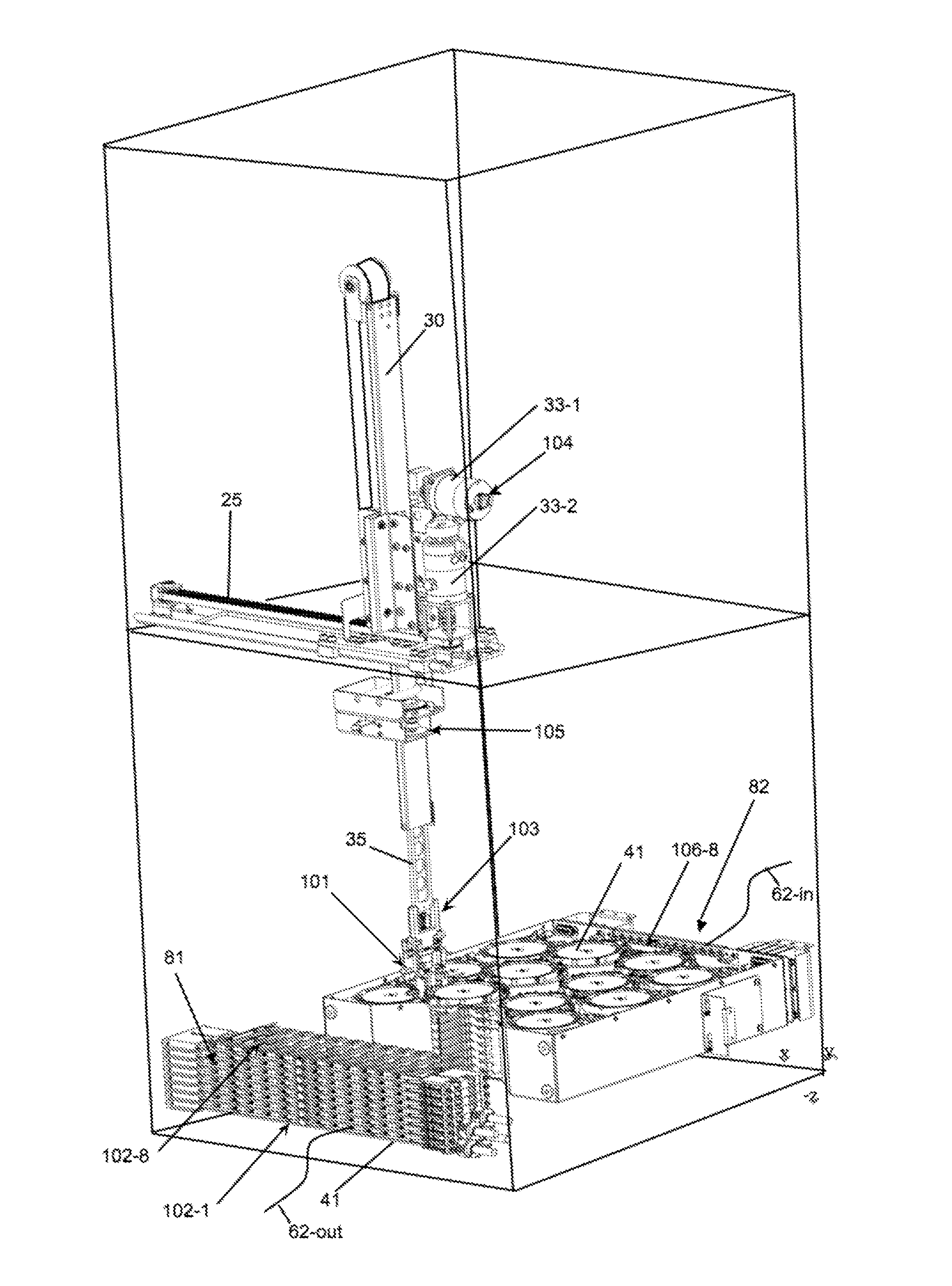
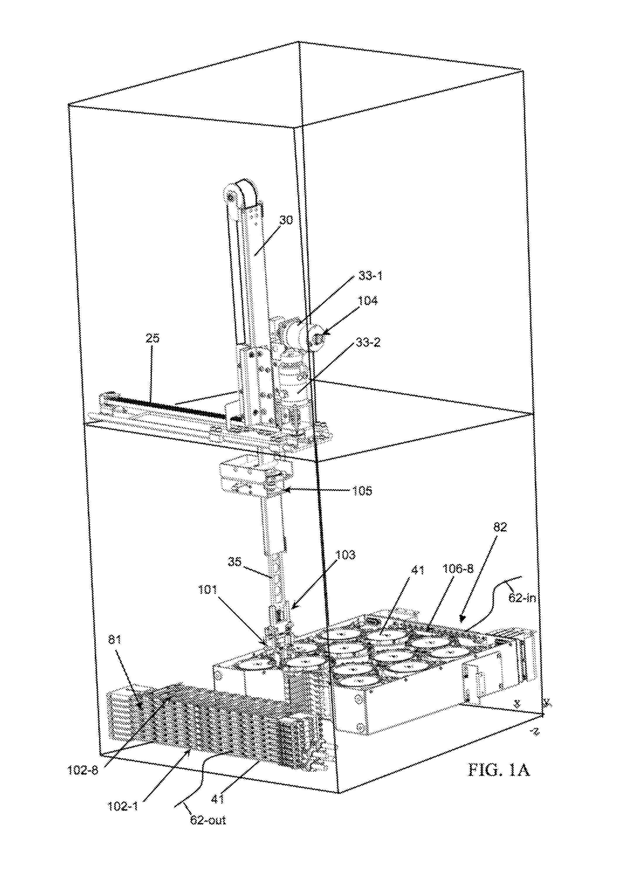
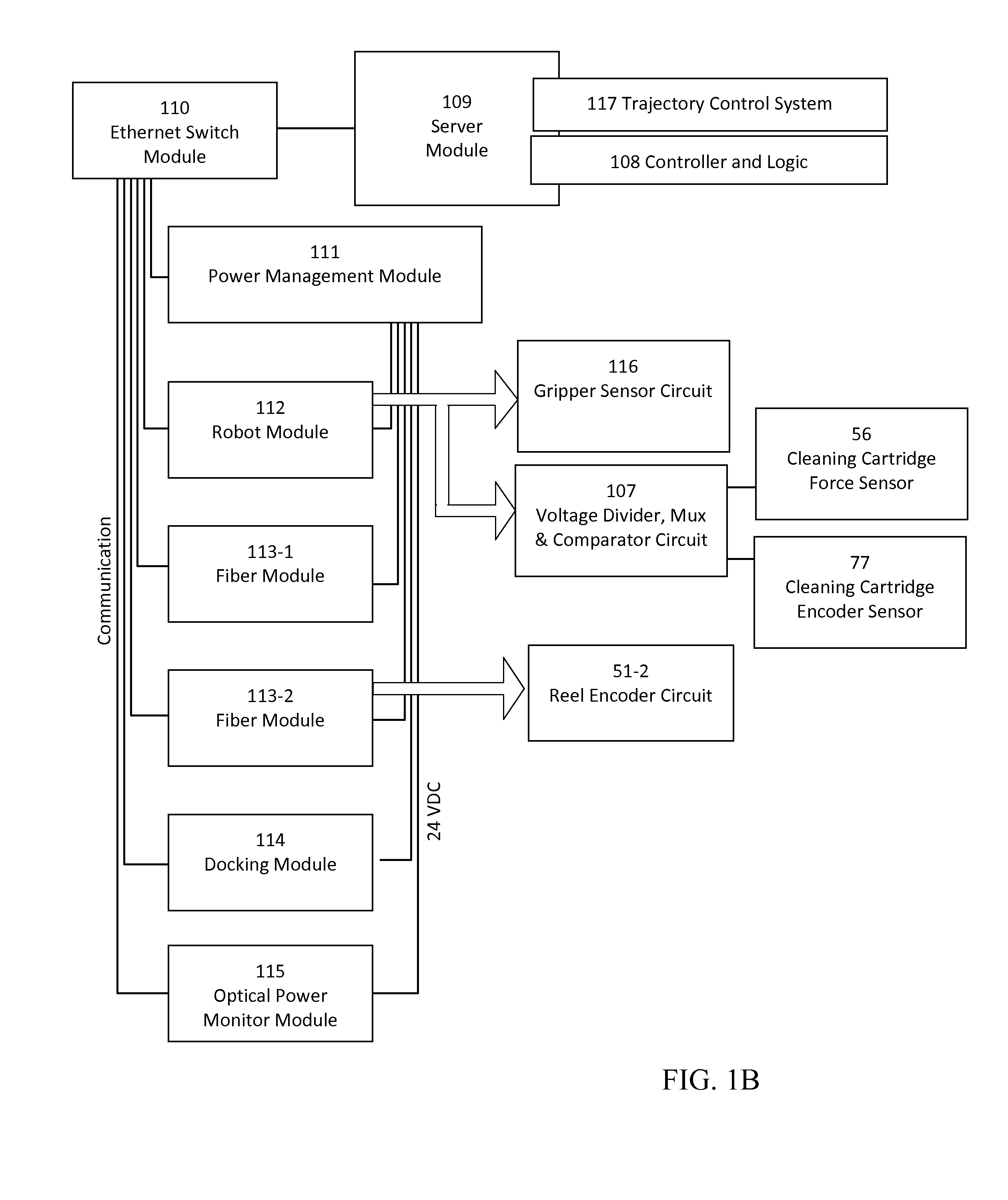
[0028]This application discloses robotic cross-connect systems providing low loss, software-defined fiber optic connections between a large number of pairs of ports. The number of ports typically ranges from 48×48 up to 1008×1008 and beyond. FIGS. 1A-1D illustrate a number of principal aspects of this system, comprised of a robot module 112 including a telescopic robot arm assembly 104, a fiber optic connector end face cleaning module 105, a miniature actuated gripper 103, a stacked arrangement of connector rows 102-1 . . . 102-N, and a stacked arrangement of fiber take-up reel trays 106-1 . . . 106-N. Groups of connector rows 102-1 . . . 102-8 further comprise the front actuated patch-panel of fiber module 113. The gripper 103 is able to unplug any fiber connector 101-n from among the array of fiber connectors inserted along the connector rows 102, then transport it in a deterministic, optimal weaving pattern between the surrounding fiber connectors o...


PUM


Abstract

Mechanisms and designs of large scale, modular, robotic software-defined patch-panels incorporate numerous features that ensure reliable operation. A telescopic arm assembly (104) with actuated gripper mechanism (103) is used to transport internally latching connectors (101) within a stacked array of translatable rows (102). A unique two-state magnetic latching feature provides reliable, low loss optical connections. Flexible, magnetically levitated internal structures are provided to assist the robot in automatically aligning to, engaging, and disengaging any internal connection in a fast reliable process within the stacked array.

Description

BACKGROUND OF THE INVENTION[0001]1. Field of the Invention[0002]The present invention is directed in general to large scale robotic cross-connect systems providing low loss, software-defined fiber optic connections between a large number of pairs of ports. Mechanisms in the systems incorporate numerous features that ensure reliable operation.[0003]2. Description of the Background Art[0004]Large scale automated fiber optic cross-connect switches and software-defined patch-panels enable data centers and data networks to be fully automated, wherein the physical network topologies are software-defined or programmable, for improved efficiencies and cost savings. Current fiber optic switch technologies such as cross-bar switches scale as N2 (N is the number of ports) making them ill-suited for large scale production networks. Prior art disclosures of cross-bar switches include U.S. Pat. No. 4,955,686 to Buhrer et al, U.S. Pat. No. 5,050,955 to Sjolinder, U.S. Pat. No. 6,859,575 to Arol et...

Claims


Application Information

Patent Timeline
14 Jul 2016
Publication
US20160202424A1
IPC
G02B6/35; G02B6/38
CPC
G02B6/3508; G02B6/356; G02B6/3556; G02B6/3866; G02B6/358; G02B6/3568; G02B6/385; G02B6/359
Inventors
KEWITSCH, ANTHONY; ZAMBOS, DON