Attachment for a hand held appliance

a technology for attaching and hand-held appliances, which is applied to spray nozzles, air heaters, apparel, etc., can solve the problems of uncomfortable touch on the outer surface of the attachment, and achieve the effects of reducing noise, reducing recirculation, and slowing down the flow

Inactive Publication Date: 2016-07-21
DYSON TECH LTD
View PDF4 Cites 61 Cited by
  • Summary
  • Abstract
  • Description
  • Claims
  • Application Information

AI Technical Summary

Benefits of technology

The patent describes a device that slows down the flow of fluid when it enters a connection, which helps to reduce noise and improve the flow of the fluid. This is achieved by increasing the cross-sectional area of the fluid flow path, which allows the fluid to attach to the walls of the connection and follow the curves, rather than hitting the walls and causing noise. Overall, this device helps to create a more laminar flow of fluid.

Problems solved by technology

The technical problem addressed in this patent text relates to how to prevent excessive heat from damaging the user's experience when using removable attachments for haidryers while still maintaining good performance and controllability.

Method used


Image

  • Attachment for a hand held appliance
  • Attachment for a hand held appliance
  • Attachment for a hand held appliance

Examples


Embodiment Construction

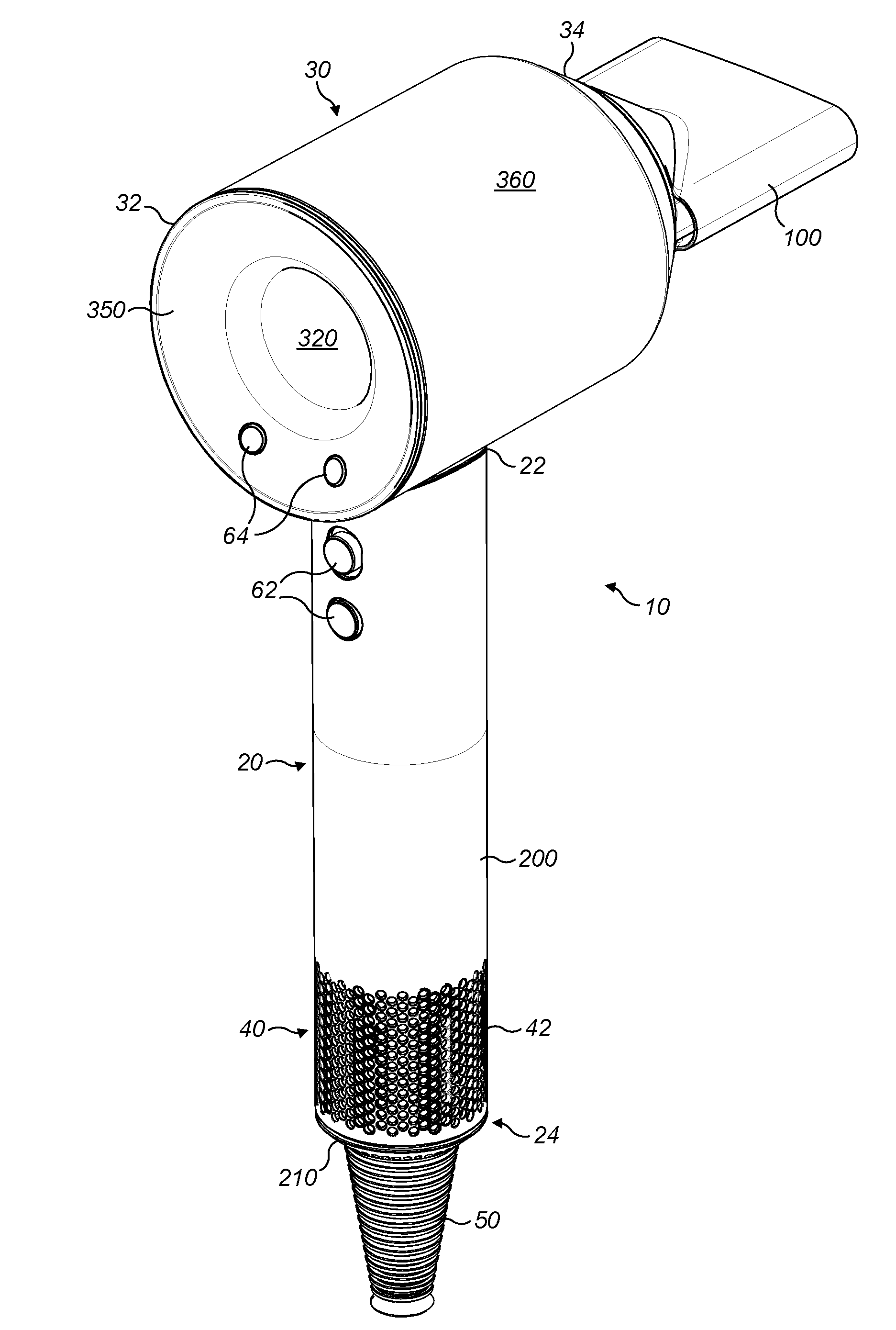
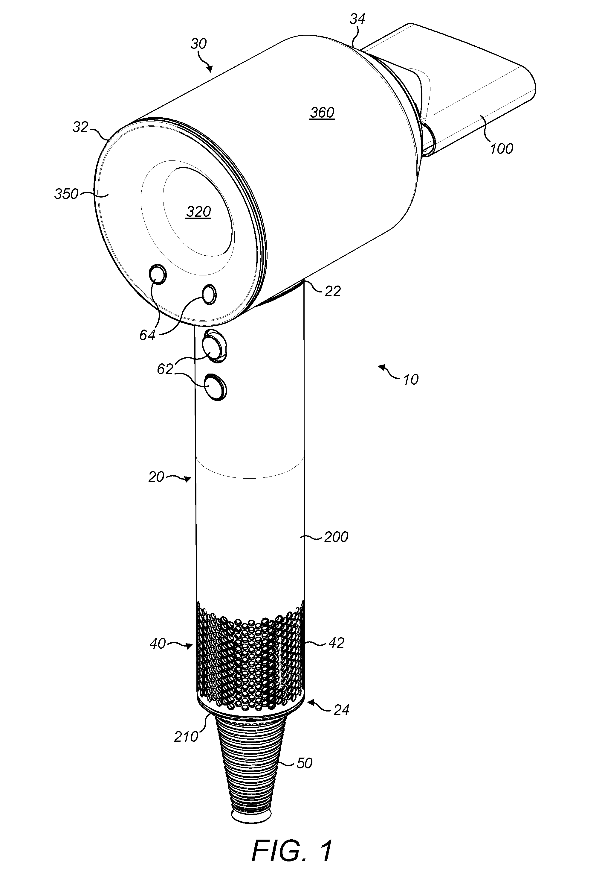
[0059]FIGS. 1 and 2 show a hairdryer 10 with a handle 20 and a body 30. An attachment 100 is connected to the hairdryer 10 in FIG. 1. The handle has a first end 22 which is connected to the body 30 and a second end 24 distal from the body 30 and which includes a primary fluid inlet 40. Power is supplied to the hairdryer 10 via a cable 50. At a distal end of the cable 50 from the hairdryer 10 a plug (not shown) is provided, the plug may provide electrical connection to mains power or to a battery pack for example.

[0060]The handle 20 has an outer wall 200 which extends from the body 30 to a distal end 24 of the handle. At the distal end 24 of the handle an end wall 210 extends across the outer wall 200. The cable 50 enters the hairdryer through this end wall 210. The primary fluid inlet 40 in the handle 20 includes first apertures that extend around and along 42 the outer wall 200 of the handle. The cable 50 is located approximately in the middle of the end wall 210 so extends from th...


PUM


Abstract

An attachment for a hand held appliance, the attachment including a first wall wherein the first wall defines a fluid flow path through the attachment extending from an annular first fluid inlet into the attachment to a first fluid outlet, wherein the fluid flow path has a cross-sectional area that expands from the first fluid inlet towards the first fluid outlet. The attachment may include a first part and a second part and the first part extends from the first fluid inlet towards the first fluid outlet and the second part extends from the first fluid outlet towards the first fluid inlet and wherein the cross-sectional area expands within the first part. The first part may be conical in shape. The second part may be elliptical or generally rectangular in shape.

Description


Claims


Application Information

Patent Timeline
Owner DYSON TECH LTD
Why Eureka
Try Eureka