

Liquid droplet discharge device
- Summary
- Abstract
- Description
- Claims
- Application Information
AI Technical Summary
Benefits of technology
Problems solved by technology
Method used
Image


Examples
Embodiment Construction
[0053]An embodiment of the invention will be described in detail below with reference to the accompanying drawings.
[0054]Here, an ink jet recording device will be described as an example of a liquid droplet discharge device.
[0055]>
[0056][Entire Structure]
[0057]First, the entire structure of the ink jet recording device will be generally described.
[0058]FIG. 1 is a schematic view showing the entire structure of the ink jet recording device.
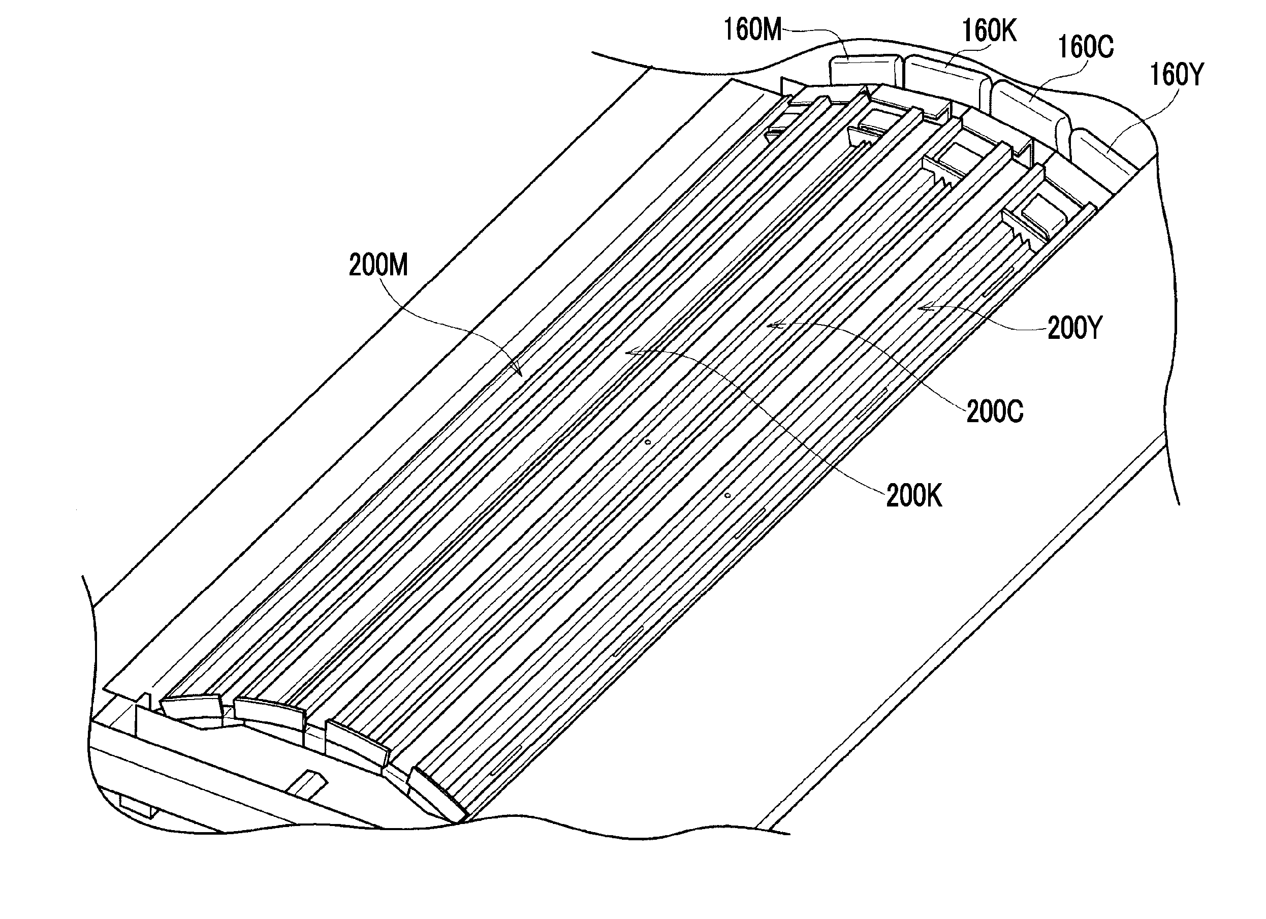
[0059]The ink jet recording device 10 shown in FIG. 1 is a color ink jet recording device that ejects ink droplets having four colors, that is, magenta (M), black (K), cyan (C), and yellow (Y) to a sheet (sheet of paper) P to draw a color image. The ink jet recording device 10 mainly includes a sheet feed section 12, a treatment liquid applying section 14, a drawing section 16, a drying section 18, a fixing section 20, a sheet discharge section 22, and a maintenance section (not shown).
[0060]
[0061]The sheet feed section 12 performs sheet feed proce...
PUM
 Abstract
Description
Claims
Application Information