
Aircraft Capable of Vertical Take-Off

a technology of vertical take-off and aircraft, which is applied in the direction of vertical landing/take-off aircraft, aircraft, transportation and packaging, etc., can solve the problems of limited cruising speed which is achievable in this manner, limited cruising speed, and only achieving relatively low cruising speed, etc., to achieve good hover characteristics and high cruising speed

Active Publication Date: 2016-07-21
AIRBUS DEFENCE & SPACE
View PDF2 Cites 167 Cited by
  • Summary
  • Abstract
  • Description
  • Claims
  • Application Information

AI Technical Summary

Benefits of technology

The patent aims to develop an aircraft that can achieve both good low-speed flying and high-speed cruising.

Problems solved by technology

Aircraft of this type are generally operated unmanned and thus can be small.
However, cruising speeds which are achievable in this manner are restricted to relatively low speeds of typically less than 200 km / h, often even less than 100 km / h, due to physical boundary conditions which arise in this type of aircraft.
A speed restriction of this type results, for example from the physical boundary condition that the propellers used for lift are operated at high rotational speeds, and therefore a propeller blade moving forwards in the direction of flight of the aircraft must move almost at sonic speed at least at the tips of the propeller blade even at relatively low cruising speeds, as a result of which a high air resistance and a loud noise are generated.
Therefore, although conventional multicopters have good hover characteristics like helicopters in which only a single rotor provides the necessary lift and complicated rotor mechanics can be used together with a tail rotor for maneuvering the helicopter, they usually only achieve relatively low cruising speeds.

Method used


Image

  • Aircraft Capable of Vertical Take-Off
  • Aircraft Capable of Vertical Take-Off
  • Aircraft Capable of Vertical Take-Off

Examples


Embodiment Construction

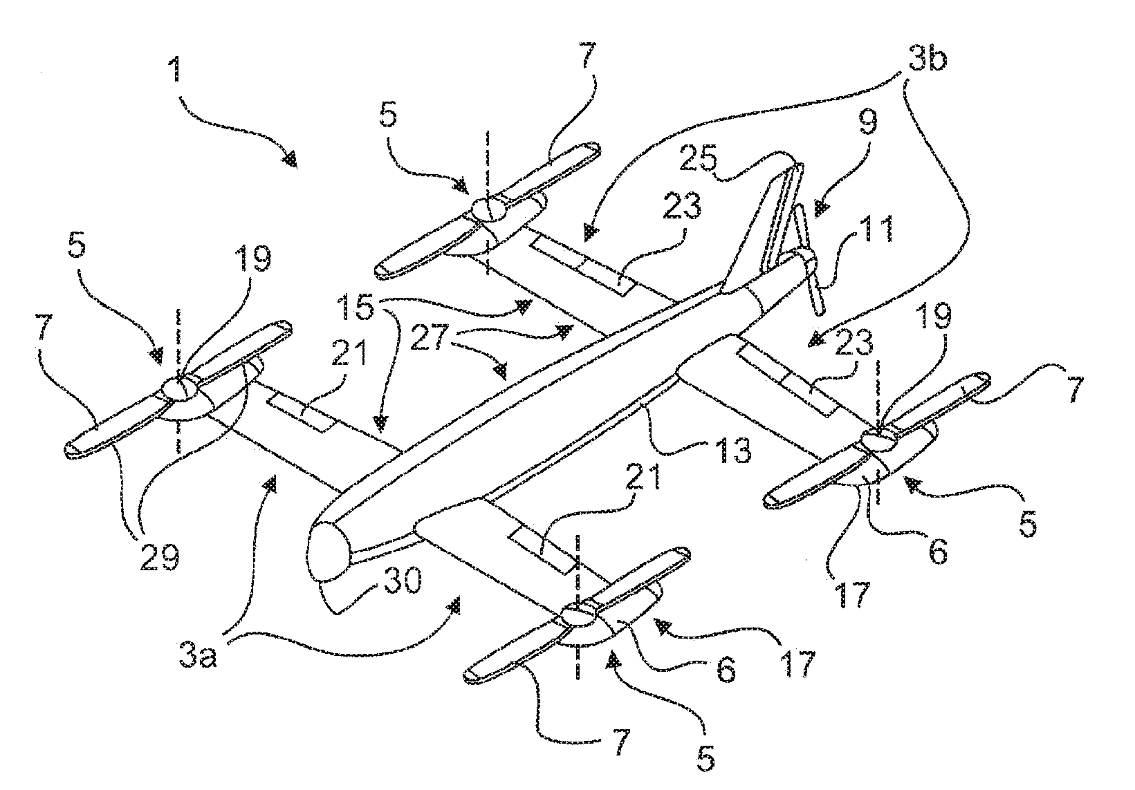
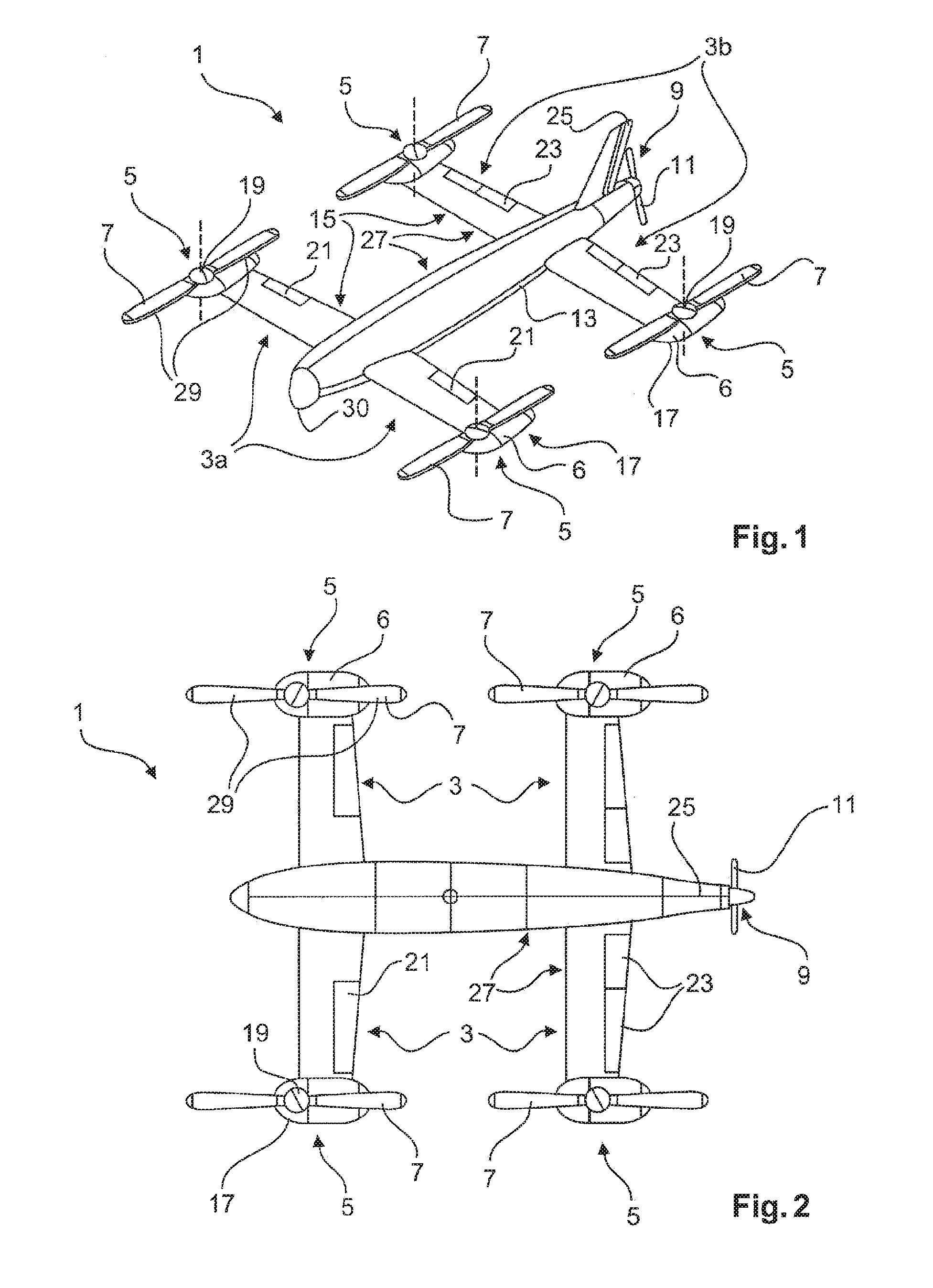
[0073]FIGS. 1 and 2 are a perspective view and a plan view of an aircraft 1 according to an embodiment of the present invention.

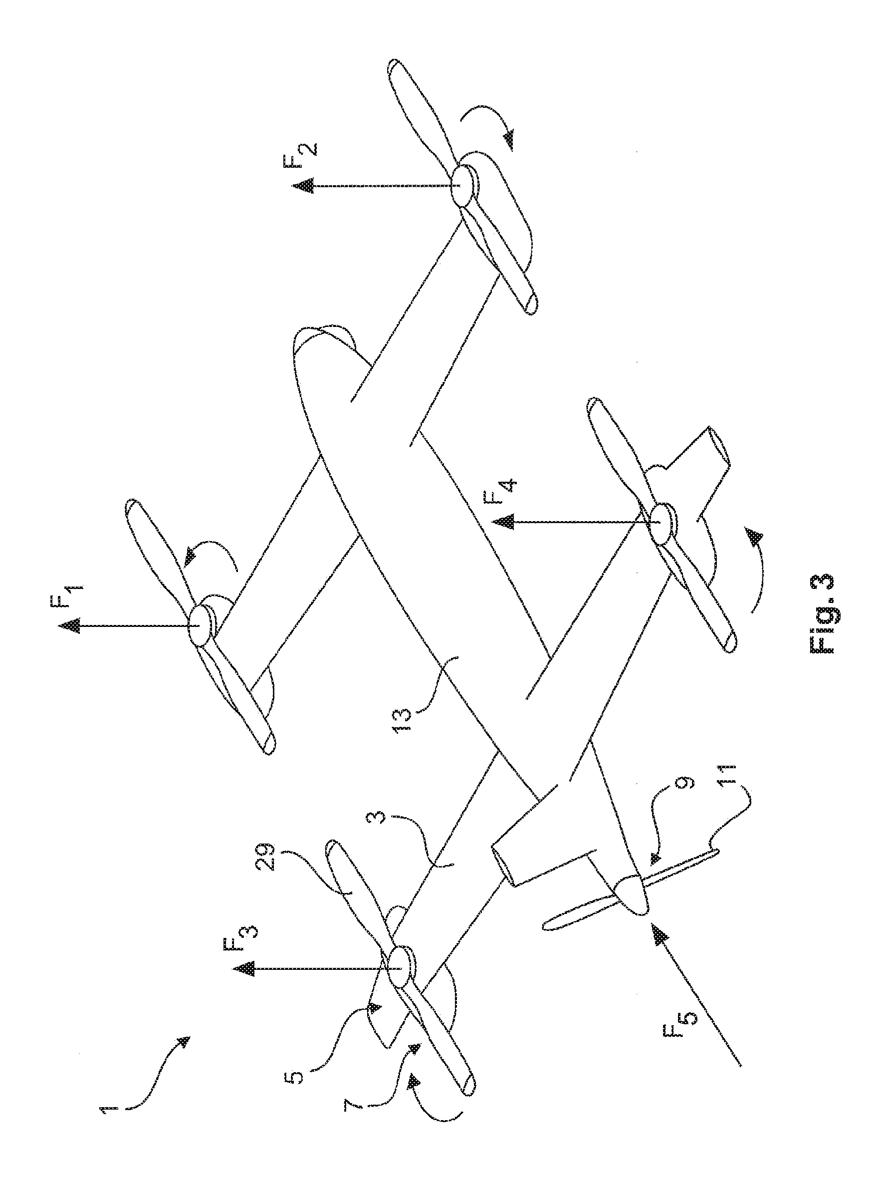
[0074]In the embodiment shown, the aircraft 1 has a tandem wing structure and, similarly to a quadcopter, one of four lifting rotors 5, fitted with a propeller 7, is arranged at both ends of each of the aerofoils 3. The lifting rotors are arranged on nacelles 6 at the ends of the aerofoils 3.

[0075]The aircraft 1 has a support structure 27 and a wing structure 15.

[0076]The support structure 27 provides the aircraft 1 with the necessary mechanical strength, for example, to transfer forces generated by the lifting rotors 5 or by the aerofoils 3 between individual regions of the aircraft 1. For this purpose, the support structure 27 has, for example, struts, stringers and formers which can form, inter alia, an elongate fuselage 13 as well as supporting parts of the aerofoils 3. The support structure can also be used to hold a camera system 30, for example,

[0077...


PUM


Abstract

The invention relates to an aircraft which can both take off and land vertically and can hover and also fly horizontally at a high cruising speed. The aircraft has a support structure, a wing structure, at least three and preferably at least four lifting rotors and at least one thrust drive. The wing structure is designed to generate a lifting force for the aircraft during horizontal motion. To achieve this the wing structure has at least one mainplane provided with a profile that generates dynamic lift. The wing structure is preferably designed as a tandem wing structure. Each of the lifting rotors is fixed to the support structure, has a propeller and is designed to generate a lifting force for the aircraft by means of a rotation of the propeller, said force acting in a vertical direction. The thrust drive is designed to generate a thrust force on the support structure, said force acting in a horizontal direction. The lifting rotors can have a simple construction, i.e. they can have a simple rigid propeller for example, and a vertical take-off or hovering of the aircraft can be controlled, in a similar manner to quadcopters, by a simple control of the speeds of the lifting rotors. High cruising speeds can be achieved as a result of the additional horizontally acting thrust drive.

Description

CROSS REFERENCE TO RELATED APPLICATIONS[0001]The present application is a National Stage of International Application No. PCT / EP2014 / 068410, filed Aug. 29, 2014, which claims the priority of German patent application No. 10 2013 109 392.2, filed on 29 Aug. 2013, the entire disclosures of which is hereby incorporated by reference.FIELD OF THE INVENTION[0002]The present invention relates to an aircraft capable of vertical take-off, for example similar to a tricopter or a quadcopter.BACKGROUND OF THE INVENTION[0003]For many uses, it is desirable to have available an aircraft which can take-off from a very small surface and which therefore does not require a specific large airport for example. Furthermore, for particular purposes of use, an aircraft is required which is agile, which can be maneuvered precisely and which can preferably hover on the spot and, in this respect, can have good hover flight characteristics.[0004]For example, aircraft are used for aerial surveillance and aerial...

Claims


Application Information

Patent Timeline
IPC IPC(8): B64C29/00B64C27/08B64C27/473B64C3/38B64C5/08B64D27/02B64D27/24B64C39/02B64C39/08
CPCB64C29/0025B64C39/024B64C27/08B64C27/473B64C39/08B64C5/08B64D2027/026B64D27/24B64C3/38B64C2201/108B64C2201/104B64C2201/165B64D27/02B64U50/13B64U10/20B64U50/33B64U50/19B64U30/29B64U50/11B64C27/22B64C29/00B64U30/10B64U30/20B64D27/026
Inventor JUDAS, MICHAELSTRATENBERG, FRIEDERIKEVAN TOOR, JANSCHOLZ, WERNERKARRAIS, BERTHOLDSTANGL, WOLFGANG
Owner AIRBUS DEFENCE & SPACE
Learn More