Watercraft vessel with a planing hull

a watercraft vessel and planing technology, applied in the direction of watercraft hull design, watercraft construction, etc., can solve the problems of not being able no known analysis of the potential to make positive use of the energy contained in the lateral spray, so as to reduce the retardation, reduce the fuel consumption, and the effect of softer rid

Active Publication Date: 2019-05-21
PETESTEP
View PDF21 Cites 2 Cited by
  • Summary
  • Abstract
  • Description
  • Claims
  • Application Information

AI Technical Summary

Benefits of technology

[0018]The object of the present invention is to provide a structure of the hull which takes advantage of all the velocity components of the whisker spray, thereby achieving an extra forward thrust that results in increased cruising speed and / or reduced fuel consumption for a given speed, as well as a higher cruising comfort.SUMMARY OF THE INVENTION
[0022]In this way, the velocity components of the lateral spray water stream are used by the present invention, by redirecting the spray to a great extent rearwardly, unlike prior art technology. Also, if configured in accordance with the invention, there will be no resistance or obstacle to water created by the deflecting surfaces, e.g. at lower speeds and / or when cruising in heavy waves. On the contrary, the water-deflecting surfaces will reduce the retardation caused by the waves or even give an extra forward thrust when the hull slams into waves.
[0023]Tests performed with hulls designed according to the present invention, compared to a corresponding prior art hull, have clearly proved that all the objectives of the invention have been fulfilled, including lower fuel consumption and a significantly softer ride.

Problems solved by technology

However, this problem has not been solved and seems to be ignored in all prior art planing hull designs.
In any case, there are no known analyses of the potential to make positive use of the energy contained in the lateral spray.

Method used


Image

  • Watercraft vessel with a planing hull
  • Watercraft vessel with a planing hull
  • Watercraft vessel with a planing hull

Examples


first embodiment

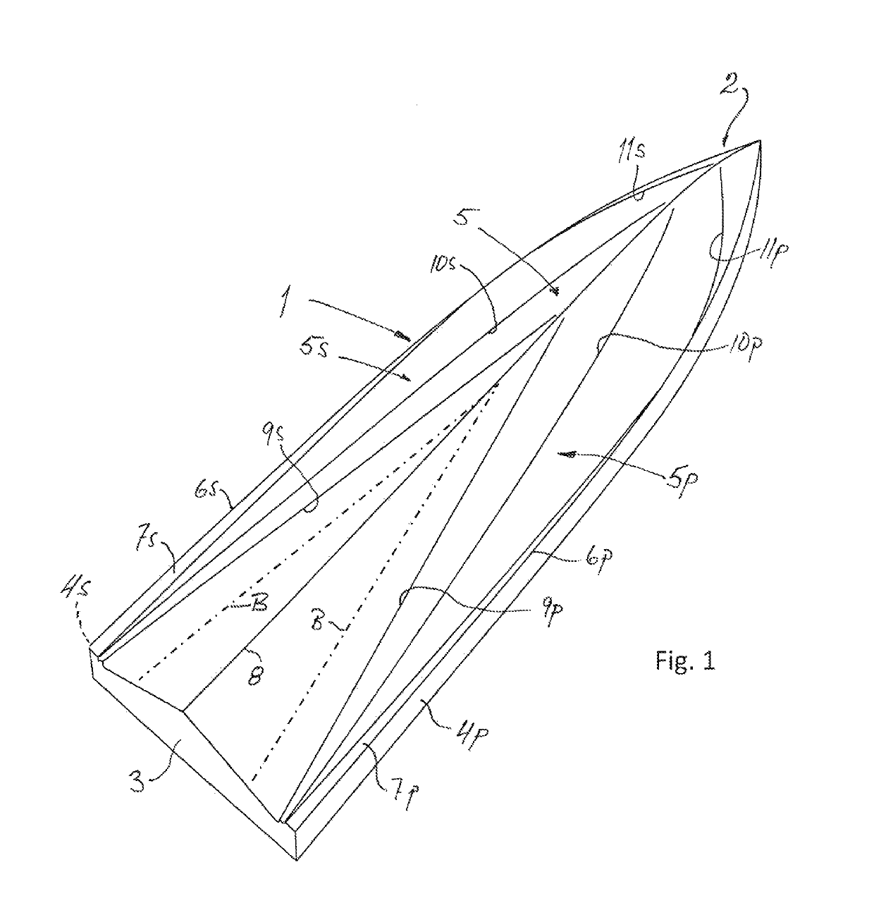
[0056]the present invention shown in FIG. 1 is a V-bottom hull 1 having a bow 2, a stern 3, hull sides 4s and 4p, a bottom 5 comprising a starboard bottom portion 5s and a port bottom portion 5p. The respective side and bottom portions are separated by a chine 6s, 6p. Conventional lifting strakes 7s and 7p are located in the respective starboard and port chine region. A longitudinal keel line 8 separates the bottom portions 5s and 5p.

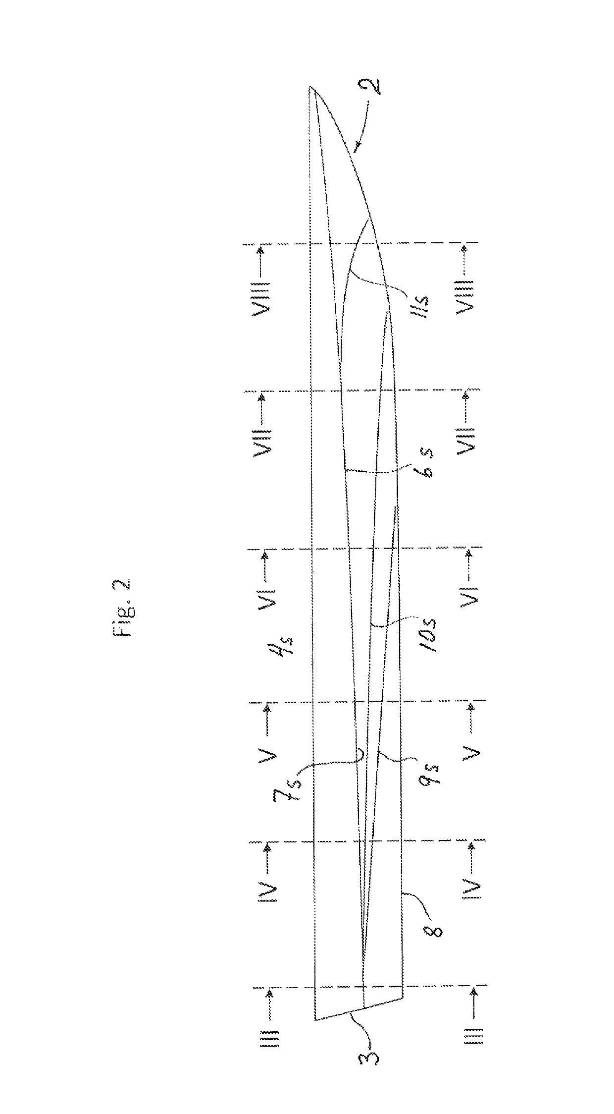
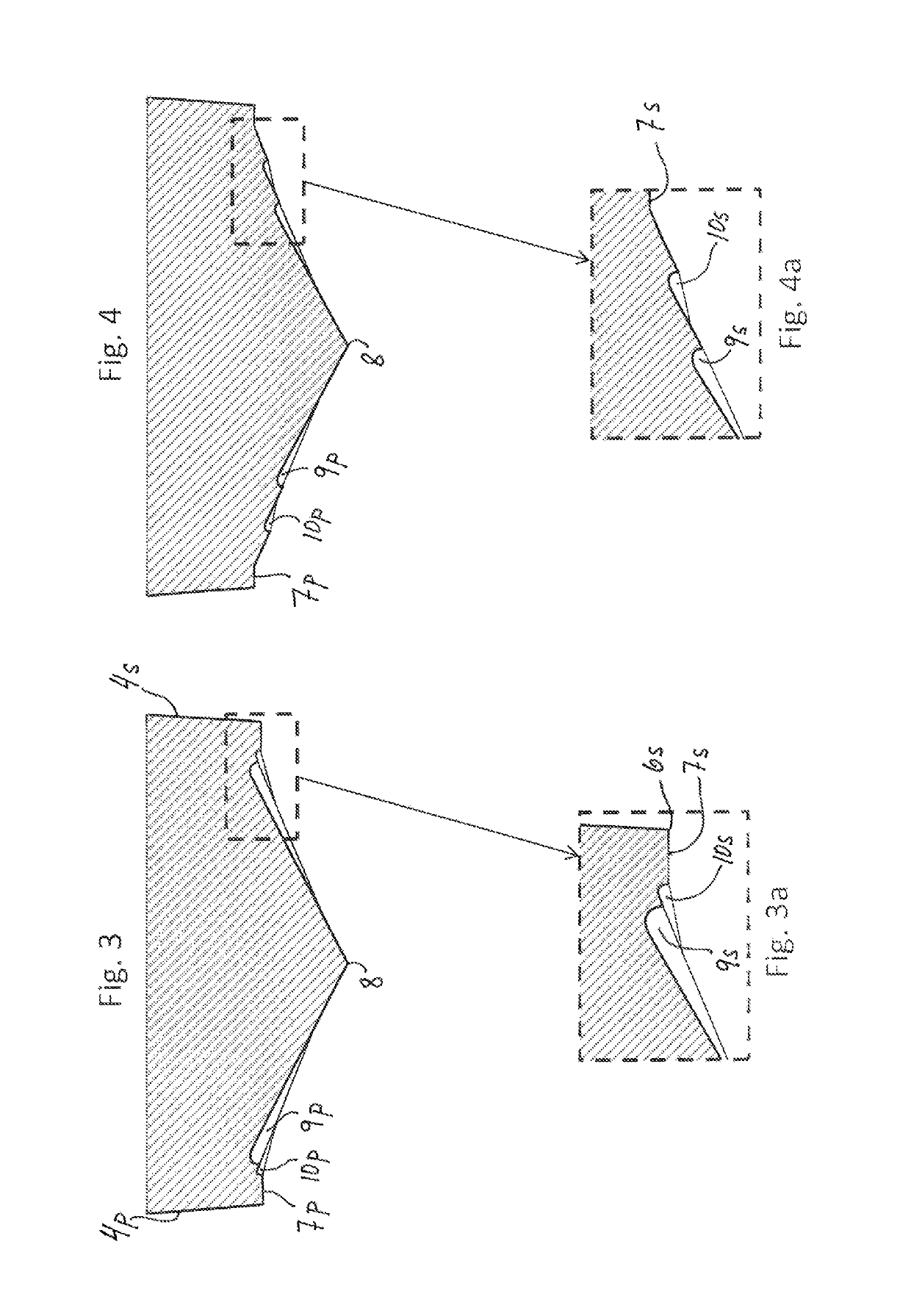
[0057]FIG. 2 shows a side view of the hull 1 of FIG. 1. Sections III-III to VIII-VIII are indicated by dashed vertical lines, marked correspondingly. These sections are shown in FIGS. 3 to 8 with respective part enlargements in FIGS. 3a to 8a. Generally, the deadrise angle in the bottom portions increases from the stern 3 to the bow 2.

[0058]A hull according to the present invention has at least one flow deflector on each bottom portion. In this first embodiment according to FIG. 1, the hull 1 has three flow deflectors on each bottom portion 5s, 5p. A f...

second embodiment

[0107]FIG. 38 shows a catamaran hull 65 embodying the present invention. It essentially corresponds to the catamaran 57 in FIG. 37, including its flow deflectors. However, in FIG. 38, each hull has a first and a second conventional, lateral step 66s, 66p and 67s, 67p, respectively, extending from where the respective second (60s, 60p) and third (61s, 61p) flow deflector starts and dividing the respective keel line into three vertically offset keel line portions 8s′, 8s″, 8s′″ and 8p′, 8p″, 8p′″, respectively. The first steps 66s, 66p end near the respective rear end of the first flow deflector 59s, 59p. Correspondingly, the second steps 67s, 67p end near the respective end of the second flow deflector 60s, 60p.

[0108]FIG. 39 shows a vertical part cross-section through a hull designed according to the present invention. A vertical longitudinal plane is indicated by a dashed line V. A flow deflector is shown to have a vertical, flat or planar flow deflecting surface 68. Furthermore, a...


PUM


Abstract

A watercraft vessel with at least one planing hull, in the form of a single unitary hull or with two or more interconnected hulls, each hull having at its bottom portion a deadrise angle in the interval 5°-70° and provided with at least one water-deflecting surface which extends rearwardly and outwardly in relation to a keel region and which is oriented and configured so as to create a lifting force, and also a forward thrust on the hull. The forward thrust is caused by a lateral spray water stream, which is redirected rearwardly by the water-deflecting surface. The latter should be located laterally outwardly of but adjacent to an approximately triangular bottom part which is submerged at the planing speed. The hull will also provide a smoother ride than conventional, planing hulls, especially in heavy sea.

Description

FIELD OF THE INVENTION[0001]The present invention concerns a watercraft vessel with a planing hull, which on one or both sides of a keel region has a bottom portion and a side portion. The vessel may comprise a unitary hull, or it may alternatively comprise two or more separate hulls that are interconnected to form for example a catamaran.[0002]More specifically, the invention concerns such a watercraft vessel that is designed for cruising at a planing speed within a predetermined speed range, normally linked to predetermined drive powers and load ranges.[0003]The bottom portion of the hull rises upwardly from the keel region towards the side portion of the hull at an angle, relative to a horizontal plane, referred to as the deadrise angle, in the interval 5°-70°, possibly varying sideways and / or along the length of the hull. Normally, the hull's bottom portion extends along the full length of the hull, measured along its water line at zero speed. The hull may have two or more longi...

Claims


Application Information

Patent Timeline
Patent Type & Authority Patents(United States)
IPC IPC(8): B63B1/18B63B1/04B63B1/16
CPCB63B1/042B63B1/18Y02T70/10B63B1/04B63B2001/005B63B2001/201B63B2001/202
Inventor BJERSTEN, PETERDANIELSSON, JONAS
Owner PETESTEP
Why Eureka
Try Eureka