

Electric vertical take-off and landing aircraft structure and working method thereof
A technology for vertical take-off and landing aircraft, applied in the field of electric vertical take-off and landing aircraft structure, which can solve the problems of poor endurance performance and low cruising efficiency, and achieve the effects of increased cruising flight speed, high take-off and cruising performance
- Summary
- Abstract
- Description
- Claims
- Application Information
AI Technical Summary
Problems solved by technology
Method used
Image

Examples
Embodiment 1
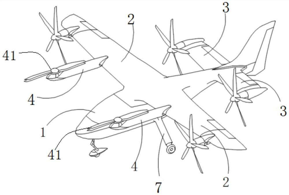
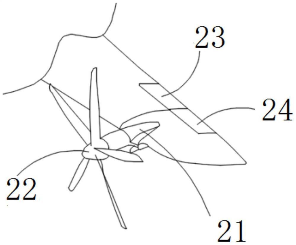
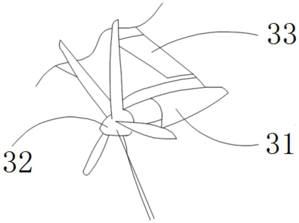
[0039] see figure 1 , an electric vertical take-off and landing aircraft structure, comprising a fuselage part 1, a wing part 2 connected to the left and right sides of the middle and upper part of the fuselage part 1, and a flat tail part 3 connected to the left and right sides of the tail of the fuselage part 1; The ends of the wing parts 2 and the ends of the left and right flat tail parts 3 are all provided with tilting propellers; the middle parts of the left and right wing parts 2 are respectively connected to the nacelle parts 4, and the nacelle parts 4 are provided with foldable propellers. Preferably, four groups of tilting propellers are arranged at the ends of the left and right wing parts 2 and the ends of the left and right flat tail parts 3, that is, four groups of power systems, and two groups of foldable propellers are arranged on the nacelle parts of the left and right wing parts 2, namely Two sets of power systems, six sets of power systems to provide power f...
Embodiment 2
[0053] Embodiment 2 of the present invention provides a structural working method of an electric vertical take-off and landing aircraft, including:
[0054] Initial stage: The aircraft is initially in a multi-rotor state. In the multi-rotor state, the left and right wing tilting nacelles and the left and right horizontal tail tilting nacelles are all rotated to 90° upward, and the foldable propellers on the nacelle parts are unfolded into a four-blade state;
[0055] Flight stage: After passengers board the plane, the six sets of power systems composed of left and right wing components, left and right horizontal tail components and left and right nacelle components provide lift to take off vertically and fly to a safe height;
[0056] Control the left and right wing tilting nacelles, and the left and right horizontal tail tilting nacelles to tilt forward slowly to provide forward flight thrust for the aircraft; the forward flight speed of the aircraft continues to increase unti...
PUM
 Abstract
Description
Claims
Application Information