Co-rotating vertical take-off and landing membrane wing aircraft

A vertical take-off and landing, co-rotation technology, applied in the direction of vertical take-off and landing aircraft, aircraft parts, wings, etc., can solve the problems of increased resistance, difficult switching operation, and difficulty in further increasing the speed, so as to reduce the demand for torque , Improve the flight speed and prolong the service life

Pending Publication Date: 2021-08-27
曾昭达
View PDF1 Cites 3 Cited by
  • Summary
  • Abstract
  • Description
  • Claims
  • Application Information

AI Technical Summary

Problems solved by technology

[0003] 1) There is a basic fixed relationship among existing aircraft: fixed-wing aircraft must adopt the taxiing take-off and landing method, while propeller-wing aircraft need to adopt the vertical take-off and landing method. Rolling take-off and landing techniques are very difficult;
[0004] 2) Fixed-wing aircraft have high requirements for take-off and landing sites. Usually, a fixed airport is required for take-off and landing. The wing is subjected to huge forces (especially during take-off and landing), and the complex working conditions cause the wing structure to be complex and its own weight is difficult to reduce. ;
[0005] 3) It is difficult for a fixed-wing aircraft to land safely once it loses power or special circumstances (such as landing gear failure, forced landing before reaching the airport, etc.);
[0006] 4) Rotor-wing aircraft generally have huge rotors, and the noise and fuel consumption are very large during flight;
[0007] 5) Once a propeller-wing aircraft loses power or has a special situation, it is equally difficult to land safely;
[0008] 6) Existing manned aircraft are expensive, difficult to ensure safety and use and maintenance, and are difficult to popularize in ordinary people's homes like cars
[0009] 7) Since the area of ​​the lower surface of the wing is fixed when the existing aircraft is flying, the resistance increases sharply after the flight reaches a certain speed, the speed is difficult to further increase, and the energy consumption is large
[0010] 8) It is very difficult for the propeller-wing aircraft to switch between landing and entering the flight state

Method used


Image

  • Co-rotating vertical take-off and landing membrane wing aircraft
  • Co-rotating vertical take-off and landing membrane wing aircraft
  • Co-rotating vertical take-off and landing membrane wing aircraft

Examples


Embodiment

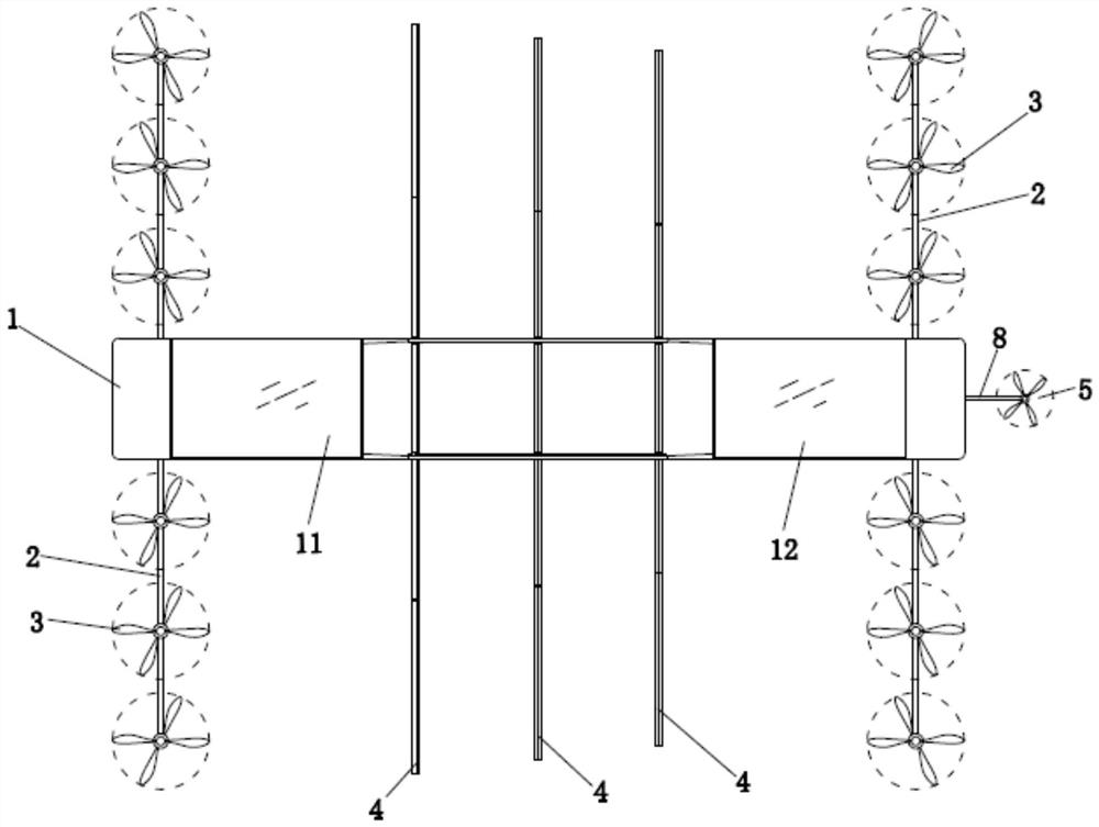
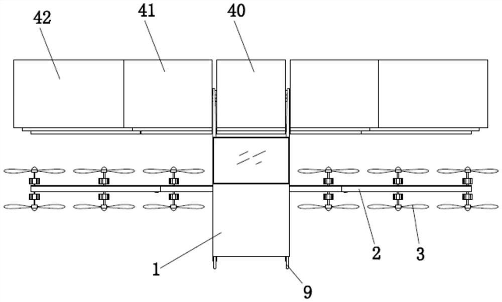
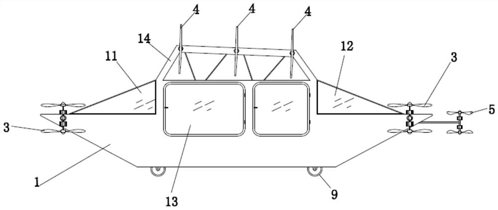
[0055] The specific embodiment of the present invention is as Figure 1 to Figure 20 As shown, a co-rotating vertical take-off and landing membrane wing aircraft includes a fuselage 1 with an aluminum alloy shell, at least two rows of power spars 2 are rotatably connected to the fuselage 1, and propellers 3 are installed on each row of power spars 2 . A membrane wing 4 rotatably connected to the fuselage 1 is arranged between adjacent power spars 2 . The middle part of the membrane wing 4 is provided with a folding angle adjusting mechanism 6 . The fuselage 1 is provided with a linkage operation device 7 for synchronously rotating the membrane wing 4 and the power spar 2 relative to the fuselage 1 . The fuselage 1 is provided with a front windshield glass 11, a rear windshield glass 12 and a plexiglass door 13. The fuselage 1 includes a wing support 14 , and each membrane wing 4 is rotatably connected with the wing support 14 . A high-energy battery providing power is hous...


PUM


Abstract

The invention discloses a co-rotating vertical take-off and landing membrane-wing aircraft. The aircraft comprises a fuselage, at least two rows of power spars are rotationally connected to the fuselage, and propellers are installed on the power spars. membrane wings rotationally connected with the fuselage are arranged between the adjacent power spars; folding angle adjusting mechanisms are arranged in the middles of the membrane wings; and the fuselage is provided with a linkage operation device which enables the membrane wings and the power spars to synchronously rotate relative to the fuselage. According to the co-rotating vertical take-off and landing membrane wing aircraft, the operation of switching between the lifting state and the flying state is simple, the speed range is large, and energy consumption is low.

Description

technical field [0001] The invention relates to the field of transportation equipment providing air transportation services, in particular to a co-rotating vertical take-off and landing membrane wing aircraft. Background technique [0002] There are many types of aircraft according to different classification methods, and they are mainly divided into two categories according to the take-off and landing methods: taxiing take-off and landing, and vertical take-off and landing. There are following deficiencies in some existing types of aircraft: [0003] 1) There is a basic fixed relationship among existing aircraft: fixed-wing aircraft must adopt the taxiing take-off and landing method, while propeller-wing aircraft need to adopt the vertical take-off and landing method. Rolling take-off and landing techniques are very difficult; [0004] 2) Fixed-wing aircraft have high requirements for take-off and landing sites. Usually, a fixed airport is required for take-off and landin...

Claims


Application Information

Patent Timeline
Patent Type & Authority Applications(China)
IPC IPC(8): B64C29/00B64C3/38B64C3/54B64C3/56B64C11/48
CPCB64C29/0033B64C3/385B64C3/546B64C3/56B64C11/48
Inventor 曾昭达曾宪越
Owner 曾昭达
Why Eureka
Try Eureka