Powered Air-Purifying Respirator

a respirator and power technology, applied in the direction of breathing masks, breathing protection, instruments, etc., can solve the problems of wearer difficulty in selecting the correct airflow level, wearer may not be able to see the visual status indicator of the turbo, and the wearer may not be able to locate and operate the turbo unit control, so as to improve the convenience of paprs and improve the effect of wired systems

Active Publication Date: 2016-07-28
3M INNOVATIVE PROPERTIES CO
View PDF6 Cites 11 Cited by
  • Summary
  • Abstract
  • Description
  • Claims
  • Application Information

AI Technical Summary

Benefits of technology

[0010]By providing a wireless remote control unit and wireless remote status indicator units, improvements in the convenience of PAPRs can be achieved, in particular, the turbo controls are more easily available to a user. By using wireless communication the positioning of the turbo remote control unit and the turbo status indicator unit is fully flexible, offering a considerable improvement over wired systems. This allows the turbo remote control unit and the turbo status indicator unit to be used by a wearer of the turbo or by a colleague positioned remotely from the user. Furthermore, by using the turbo unit power source to power the electronic control transceiver only one battery or other power supply needs to be recharged to ensure that the entire turbo unit is operable.

Problems solved by technology

In these circumstances it may be difficult for the wearer to locate and operate turbo unit controls especially if they out of the range of vision of the wearer.
For example, if a turbo unit is provided with an airflow level adjustment as described above, it can be difficult for the wearer to select the correct airflow level if the turbo is out of sight.
Furthermore, the wearer may not be able to see visual turbo status indicators that are mounted on the turbo unit.
The above-described situation is often exacerbated by the fact that PAPR wearer containment environments, such as head pieces or masks, can restrict the wearer's peripheral vision thereby limiting the wearer's range of vision.
Furthermore, it is often not possible for the wearer to see any turbo unit mounted visual turbo status indicators.
Such wired solutions as described above provide limited positioning options to suit individual wearer's preference and / or job related preference.
The positioning of wired turbo status indicators is often limited to being worn by the PAPR wearer.
In many workplace situations, for example working close to rotating machines, the use of wired cables is unlikely to be acceptable due to problem of snagging or entanglement of wires.

Method used


Image

  • Powered Air-Purifying Respirator
  • Powered Air-Purifying Respirator
  • Powered Air-Purifying Respirator

Examples


Embodiment Construction

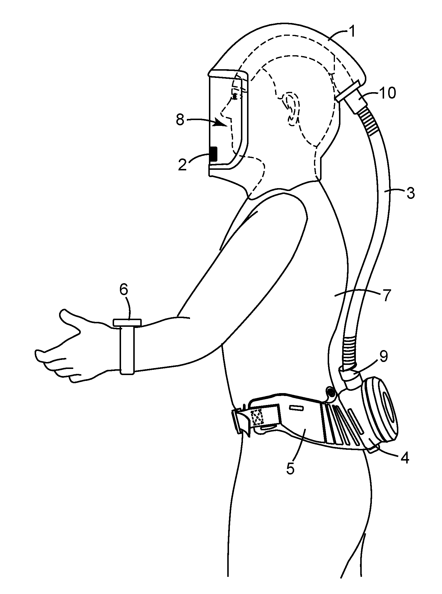
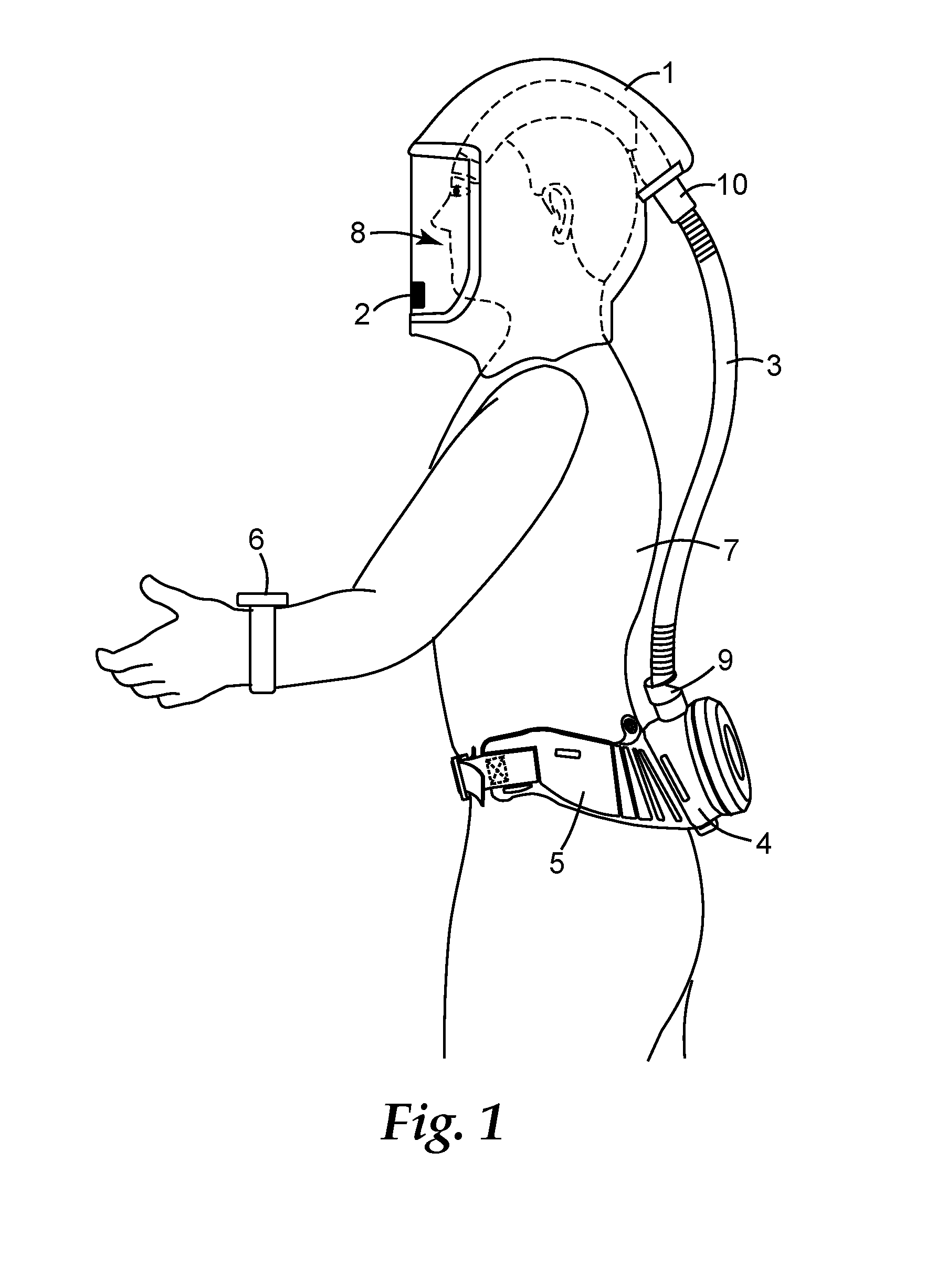
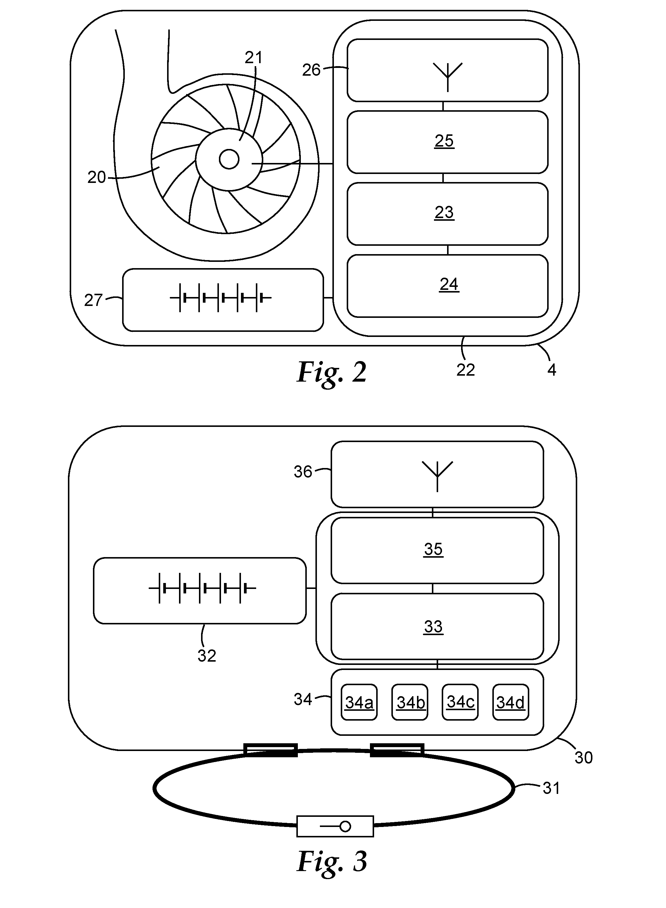
[0022]It has been realised that increased flexibility can be given to the wearers of powered air purifying respirators by taking advantage of wireless technology. Turbo controls and turbo status indicators may be provided in wireless units that can be located either about the wearer's body or remote from the wearer based on the needs of the wearer or the particular job that they are carrying out. Turbo controls, such as on / off switch and airflow adjustment and turbo status indicators, for example, indication of normal operation, low airflow indication, filter change indication, or low battery indication, are common features of PAPRs that can be made more accessible by the present invention.

[0023]Wireless technology includes networks such as broadcast networks and closed loop networks. Broadcast communications are wireless systems where a transmitter sends out a signal that is received by any compatible receiver that is within range of the transmitter. A closed loop network in terms ...


PUM


Abstract

A powered air purifying respirator (PAPR) for delivering a forced flow of filtered air to a wearer is disclosed. The PAPR comprises a turbo unit with turbo unit components including a fan, an electric motor, and an electronic control unit having a wireless electronic control transceiver, the fan being driven by the electric motor under the control of the electronic control unit and the electronic control unit being configured to send and receive information via the electronic control transceiver; a turbo unit power source that provides power to the turbo unit components; a turbo remote control unit having a wireless turbo remote control transceiver; at least one turbo status indicator unit, adapted to indicate a current operating status of the turbo unit and / or turbo unit components, having a wireless turbo status transceiver; wherein at least one of the turbo remote control unit and turbo status indicator unit is remote from the turbo unit, and wherein at least two of the electronic control transceiver, the turbo remote control transceiver and the turbo status transceiver are in wireless communication with each other.

Description

[0001]The present invention relates to a Powered Air Purifying Respirator (PAPR) for delivering a forced flow of filtered air to a wearer.BACKGROUND[0002]A powered air purifying respirator (PAPR) is a common type of respirator used when working in areas where there is known to be, or there is a risk of there being, dusts, fumes or gases that are potentially hazardous or harmful to health. A PAPR has a turbo unit comprising a fan driven by an electric motor for delivering a forced flow of air to the respirator wearer. One or more filters are fitted to the turbo unit through which air is drawn by the fan. The air is passed from the turbo unit through a breathing tube to a contained wearer environment, such as a face piece, a head piece or a suit, thus providing filtered air to the wearer's breathing zone (the area around their nose and mouth, known as the orinasal area).[0003]A turbo unit for a PAPR may have an electronic control unit to regulate the power driving the fan. Typically, ...

Claims


Application Information

Patent Timeline
Patent Type & Authority Applications(United States)
IPC IPC(8): A62B9/00A62B18/04A62B23/02
CPCA62B9/006A62B18/045A62B23/02A62B7/10A62B18/08A62B18/006G08C17/02
Inventor CURRAN, DESMOND T.MURPHY, ANDREWWALKER, GARRY J.SAYERS, TERENCE M.HENDERSON, CHRISTOPHER P.KALLMAN, BENGT
Owner 3M INNOVATIVE PROPERTIES CO
Why Eureka
Try Eureka