Combination of unmanned aerial vehicles and the method and system to engage in multiple applications

a technology of unmanned aerial vehicles and combined vehicles, applied in vehicle position/course/altitude control, process and machine control, instruments, etc., can solve the problems of absolutely challenging and extremely costly the engagement of multiple missions

Inactive Publication Date: 2016-07-28
DE SILVA SHELTON GAMINI
View PDF4 Cites 327 Cited by
  • Summary
  • Abstract
  • Description
  • Claims
  • Application Information

AI Technical Summary

Benefits of technology

[0013]Further, object of the present invention is to provide a system that the Sub UAV members are capable of storing collected data from a specific location and transmits said data to the Main UAV member immediately or at a later time. The basic principle is to collect data, store data and transmit collected data via satellites to the Data Station members to analyze and use for various purposes. Storing the data is one of the most important feature of the Sub UAV system, because when satellites are unable to obtain data at a specific time, due to weather, location of the satellites, distance where data is collected, or any other reason, the Sub UAV members are able to collect said data, store and transmit to the satellites when they are ready to receive. This will solve todays' issues of obtaining a steady stream of satellite data. It is important to note that, the Main UAV member is also able to receive accurate data from the Sub UAV members while flying at a selected altitude in the area.
[0015]Still another object of the present invention is to provide a remote and satellite communication capability wherein, the Mother UAV member receives and transmits command signals between Data Station members, between Sub UAV members, whereby the Sub UAV members are capable of receiving command signals assembly from Mother UAV member and Data Control Station member so that the Sub UAV members are able to fly in a sequence and coordinated manner alongside the Mother UAV, and capable to maneuver and perform a specific action.
[0016]Further, object of the present invention is to provide a firm, safe and secure Sub UAV releasing and receiving system and mechanical locking system, wherein Mother UAV member is able to eject and receive Sub UAV members at high, low or mid altitude, while minimizing any accident and damage to any of said UAV members.
[0018]Another object of the invention is that the Sub UAV members are ejected from the Mother UAV members and lands on the ice or middle of the ocean or any appropriate location, and has the capability to move from one location to another where data needs to be collected. Once it lands, the hover engines will turn upright and provide power to move the Sub UAV member from one location to another as an unmanned hovercraft. This provides an opportunity to find a specific location that needs to be investigated, also allowing transporting any samples to near by data stations. It is important to note that these vehicles are designed for use in onshore and offshore by modifying the Sub UAV to change into a hovercraft capable of travelling over ice, water, land or mud.
[0023]Further, the present invention provides fixed wings connected to both sides of the flatbed area, also a pair of horizontal stabilizers and vertical stabilizers that extends from the end of the flatbed area. The Mother UAV member operates with turbine engines, which provides a high-speed capacity, which are mostly located under the wings, and it is important to note that these engines may be located in a different location based on specific requirements, especially to be used for military purpose to gain high velocity. However, these changes are within the sprit and scope of the present invention. Jet engine of the Main UAV member is designed varying in sizes, shapes and wing configurations. Further, provides that the jet engines to be rotated upwards for vertical takeoff and landing, this configuration also supports the Mother UAV member to be more stable and controlled in mid air during releasing and receiving Sub UAV members.
[0025]The Sub UAV member consists of a more different structure and operating system than the Mother UAV member. The external configuration of the Sub UAV member remains unchanged, and inner structure of the Sub UAV member changes according to a specific application. For example, when said Sub UAV member is used to combat oil spills the Sub UAV member would be constructed with the ability to carry booms or fire retardant substance. When said Sub UAV member is used for Arctic drilling it would comprise with a complete mechanical system and so on. The Sub UAV member operates with two operating modes, the rotorcraft in which lift and thrust are supplied by rotors similar to the helicopter, also comprises of a hover operating capability wherein Sub UAV member is able to easily land on the ground or water, and move from one location to another. On the other hand hover engines also assist for careful landing capability on the flatbed of the Mother UAV member when it returns.

Problems solved by technology

Nevertheless, to engage in said multiple missions are absolutely challengeable and extremely costly, since each of these missions need specific actions, diverse equipment and human involvement.

Method used


Image

  • Combination of unmanned aerial vehicles and the method and system to engage in multiple applications
  • Combination of unmanned aerial vehicles and the method and system to engage in multiple applications
  • Combination of unmanned aerial vehicles and the method and system to engage in multiple applications

Examples


Embodiment Construction

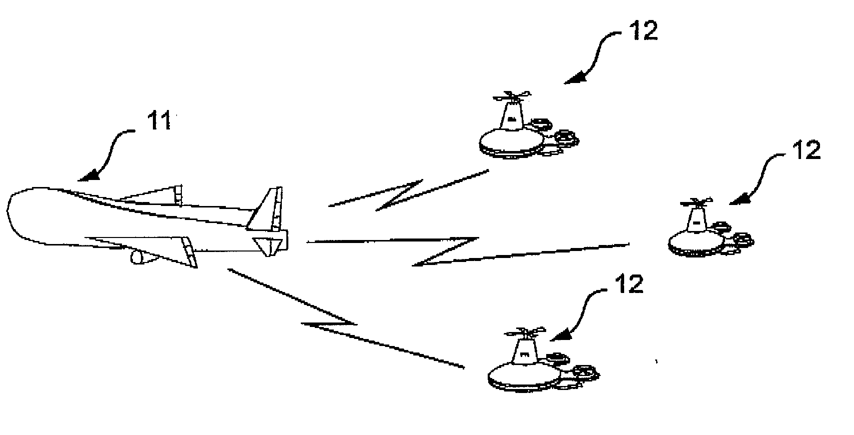
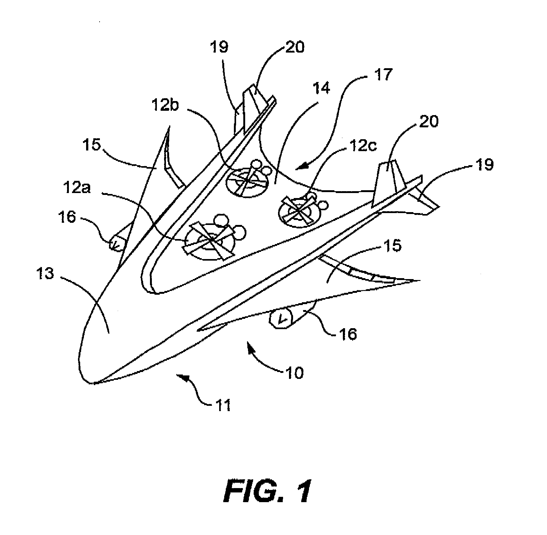
[0035]In particular to the drawings FIGS. 1-8, illustrates the Mother UAV member that carries modules of Sub UAVs generally designed by the reference numerical 10. Reference more particularly to the drawings 10 describes the top view of the Mother Unmanned Aerial Vehicle “Mother UAV” member 11, consists of a high front nose section member 13, and wider back section with flatbed surface member 14, which carries Sub UAV members 12A 12B and 12C. Further, comprises of a method and system that the Mother UAV member 11 is able to eject the Sub UAV member 12 in mid air, so that said Sub UAV member 12 is able to operate autonomously and land on a specified area and engage in a specific mission. Further, consists of a system and method that said Sub UAV member 12 is capable to return to the Mother UAV member 11 and land on the flatbed area member 14. In addition, includes wing members 15 on each side of the Mother UAV member 11, mounted with jet engine assemblies member 16 with the Tilt Roto...


PUM


Abstract

This invention relates to an Unmanned Aerial Vehicle hereinafter called “Mother UAV” member (11) capable of carrying modules of Sub Unmanned Aerial Vehicle members (12) hereinafter called “Sub UAV” member. More particularly, the method and system that is capable of communicating via satellite and remote control technology wherein ejecting said Sub UAV members (12) from the Mother UAV member (11) wherein Sub UAV members (12) autonomously fly in sequence in a coordinated manner with the Mother UAV member (11), and capable of engaging in multiple missions in high, medium, low altitude, and surface, also communication with under sea submarines (27). Further, comprises of a method and system that the Sub UAV members (12) are able to return back to the Mother UAV member (11) after the mission is completed and be firmly secured to the flatbed (14) of the Mother UAV member (11). The present invention is specifically designed for multifunctional and multipurpose applications where humans and other vehicles are unable to access, for civil, commercial and military purposes.

Description

FIELD OF THE INVENTION[0001]This invention relates to a flatbed featured Unmanned Aerial Vehicle hereinafter called “Mother UAV” member capable of carrying modules of Sub Unmanned Aerial Vehicle members hereinafter called “Sub UAV” member securely fastened on the flatbed area of the Mother UAV. More particularly, the method and system that is capable of ejecting said Sub UAV members from the Mother UAV member wherein Sub UAV members autonomously fly in sequence in a coordinated manner with the Mother UAV member, and capable of landing in a specified location, also the method and system that the Sub UAV members are able to return back to the Mother UAV member, and be firmly secured on the flatbed of the Mother UAV member. Further, Mother UAV member comprises of a system that the Mother UAV member and Sub UAV members communicate with each other via satellite and remote control technology to send and receive command signals between said UAV members, also to communicate with moveable or...

Claims


Application Information

Patent Timeline
Patent Type & Authority Applications(United States)
IPC IPC(8): B64D5/00G05D1/10G05D1/00B64C39/02B64D47/08
CPCB64D5/00B64C39/024G05D1/104G05D1/0011B64D47/08H04L67/12Y04S40/18B64U70/20B64U10/25B64U2101/20B64U2101/00B64U10/10B64U2201/102B64U2201/104B64U80/82
Inventor DE SILVA, SHELTON GAMINI
Owner DE SILVA SHELTON GAMINI
Why Eureka
Try Eureka