
Beat tone full waveform inversion

Active Publication Date: 2016-07-28
ADVANCED GEOPHYSICAL TECH
View PDF0 Cites 27 Cited by
  • Summary
  • Abstract
  • Description
  • Claims
  • Application Information

AI Technical Summary

Benefits of technology

[0006]The present disclosure provides for a method for generating a model of an underground formation from seismic data. The method may include measuring seismic data from one or more receivers in the time domain. The one or more receivers may be positioned to receive seismic waves generated by a source and emitted into the underground formation, the seismic waves forming the seismic data. The method may further include converting the seismic data from the time domain to the frequency domain to form frequency domain seismic data. The method may further include extracting, from the frequency domain seismic data, first measured frequency domain data from corresponding to a first signal at a first frequency. The method may further include extracting, from the frequency

Problems solved by technology

Because of hardware limitations of geophones and hydrophones, seismic data is typically band limited, rendering low frequency seismic data unavailable.
Due to the lack of low frequency data, large underground structures are less able to be identified due to issues including without limitation nonlinearity of the FWI and the cycle-skipping phenomenon.
Nonlinearity and cycle-skipping can result in incorrect data fitting as, for example, the inversion may be trapped in local minima, preventing the updated models from progressing properly.

Method used


Image

  • Beat tone full waveform inversion
  • Beat tone full waveform inversion
  • Beat tone full waveform inversion

Examples


Embodiment Construction

[0016]It is to be understood that the following disclosure provides many different embodiments, or examples, for implementing different features of various embodiments. Specific examples of components and arrangements are described below to simplify the present disclosure. These are, of course, merely examples and are not intended to be limiting. In addition, the present disclosure may repeat reference numerals and / or letters in the various examples. This repetition is for the purpose of simplicity and clarity and does not in itself dictate a relationship between the various embodiments and / or configurations discussed.

[0017]In the following disclosure, it is to be understood that frequency of a signal may be expressed as either ordinary frequency, commonly measured in cycles per second or Hz, or angular frequency, measured in radians per second. As used herein, f refers to ordinary frequency and co refers to angular frequency. One having ordinary skill in the art with the benefit of...


PUM


Abstract

A full wave inversion (FWI) may utilize an Amplitude-Frequency-Differentiation (AFD) or a Phase-Frequency-Differentiation (PFD) operation to form a velocity model of a subterranean formation utilizing recovered low wavenumber data. Received seismic data is processes to isolate two data signals at different frequencies. In an AFD operation, the two data signals are summed and the data of the envelope of the summed function is used for the FWI. In a PFD operation, the phase data of the quotient of the two data signals is used for the FWI. The FWI proceeds iteratively utilizing either the AFD or PFD data or with single frequency data until the cost function of the AFD or PFD is satisfied.

Description

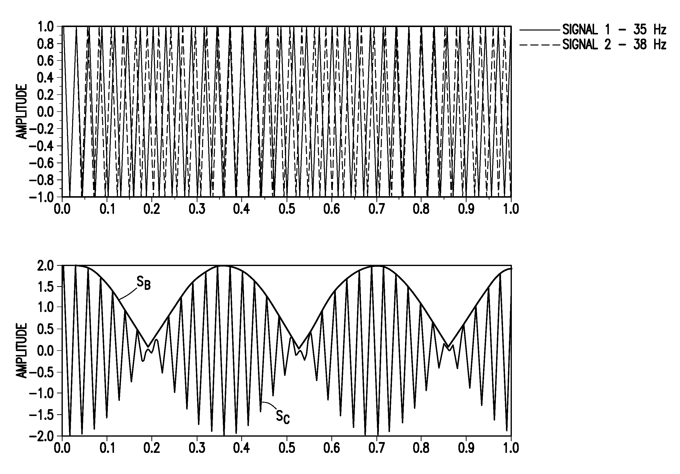
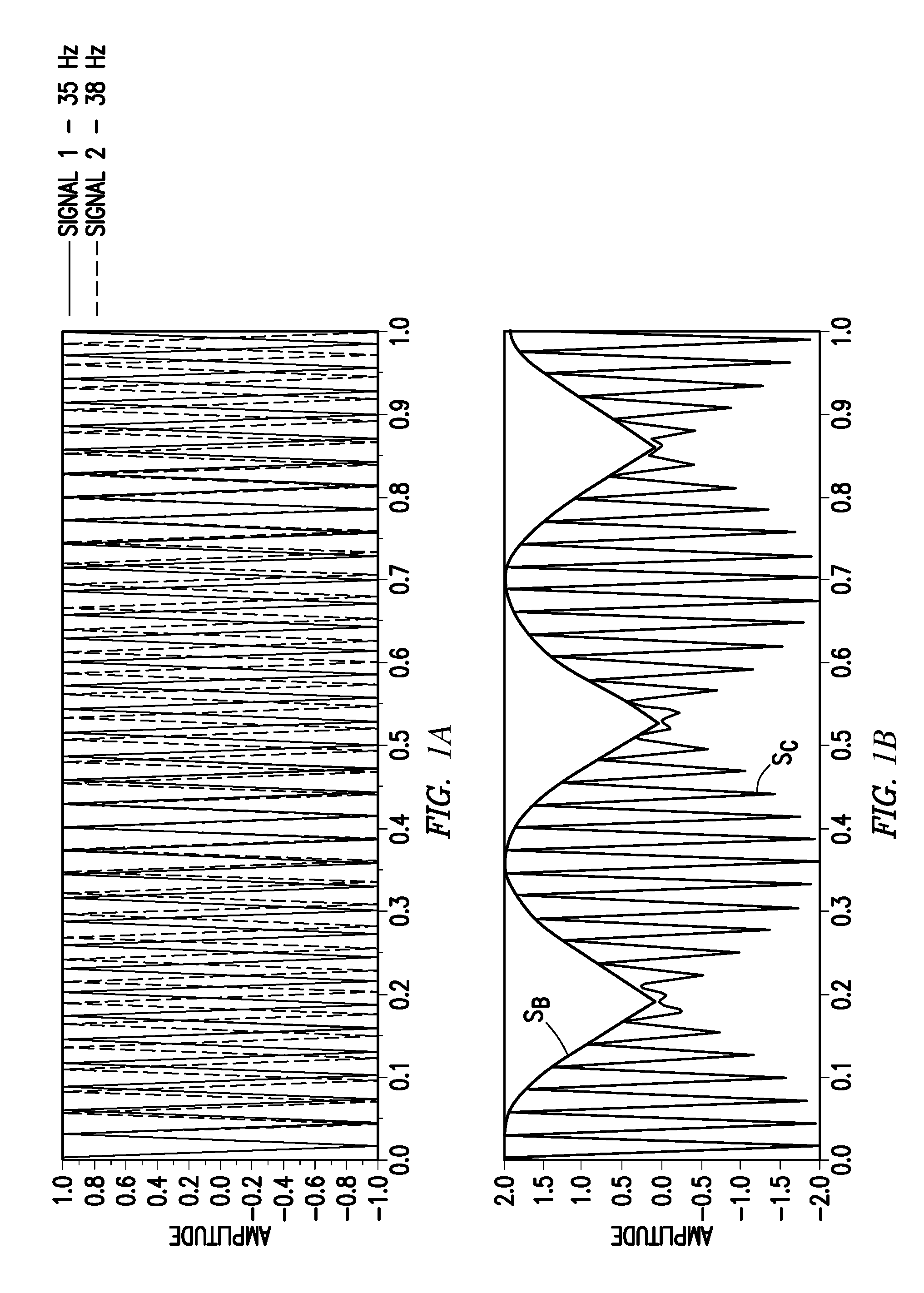
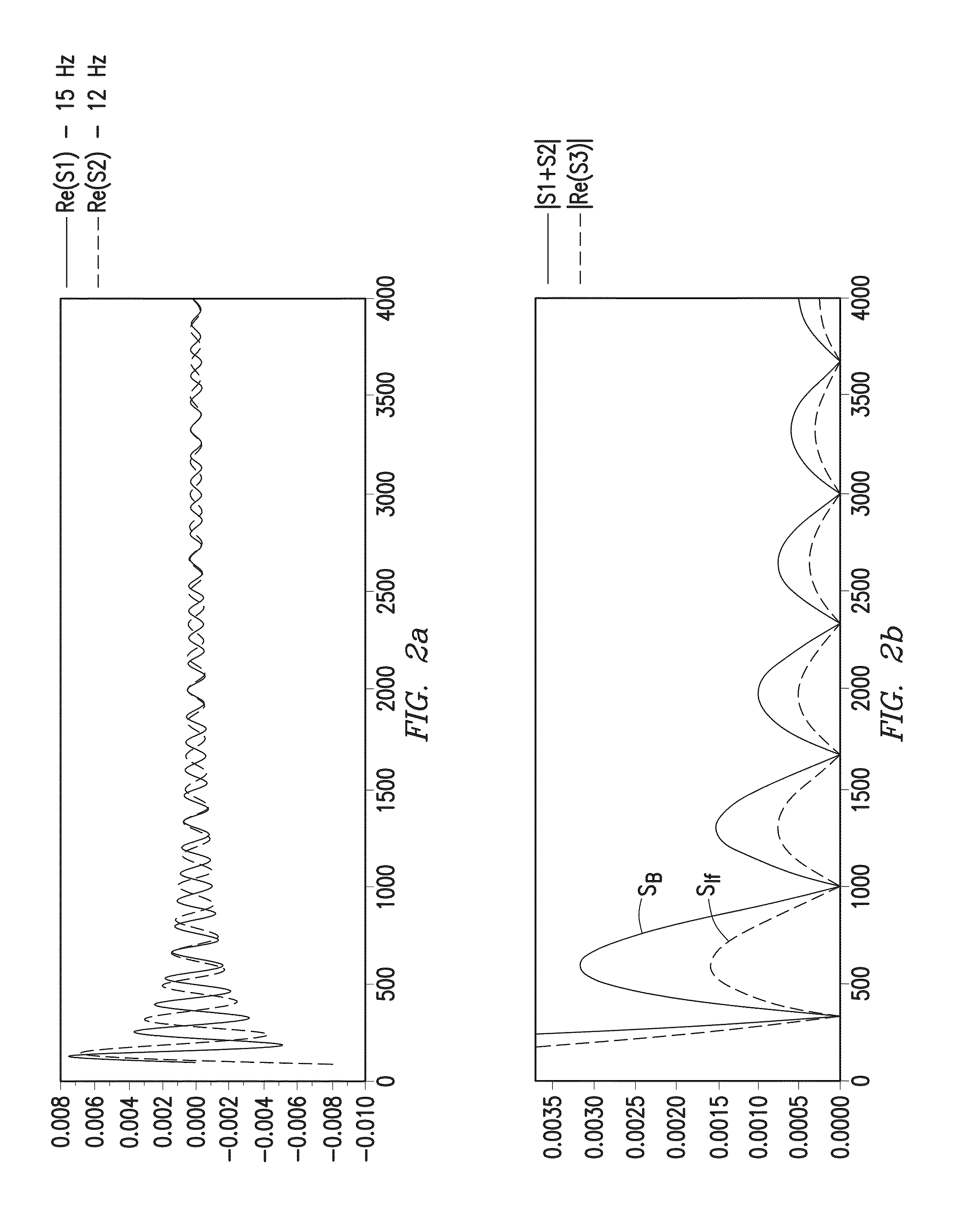
CROSS-REFERENCE TO RELATED APPLICATIONS[0001]This application is a nonprovisional application which claims priority from U.S. provisional application No. 62 / 107,025, filed Jan. 23, 2015, the entirety of which is hereby incorporated by reference.TECHNICAL FIELD / FIELD OF THE DISCLOSURE[0002]The present disclosure relates to processing of seismic data.BACKGROUND OF THE DISCLOSURE[0003]In order to determine the composition and structure of an underground formation, seismic data may be utilized. As understood in the art, when a seismic wave propagates through the earth from a source to a receiver, the received seismic wave may bring information about geophysical properties of the subsurface volume. The properties may include, without limitation, seismic wave velocity, mass density, and anisotropy properties. In exploration geophysics, by recording the seismic waves at the surface by one or more geophones or hydrophones, a model of the subsurface strata may be determined through various s...

Claims


Application Information

Patent Timeline
IPC IPC(8): G01V1/28G01V1/30
CPCG01V1/282G01V2210/679G01V1/303G01V1/325G01V2210/43G01V2210/614G01V2210/6222G01V2210/66G01V2210/675
Inventor HU, WENYI
Owner ADVANCED GEOPHYSICAL TECH
Learn More