Quantum interference device, atomic oscillator, electronic apparatus, and moving object

Inactive Publication Date: 2016-07-28
SEIKO EPSON CORP
View PDF3 Cites 38 Cited by
  • Summary
  • Abstract
  • Description
  • Claims
  • Application Information

AI Technical Summary

Benefits of technology

[0033]With this configuration, it is possible to provide the moving object in

Problems solved by technology

However, in the atomic oscillator described in Patent Literature 1, since an emitted light amount changes according to the change in the bias current, frequency stability (in particular, long-term frequency stability) is d

Method used


Image

  • Quantum interference device, atomic oscillator, electronic apparatus, and moving object
  • Quantum interference device, atomic oscillator, electronic apparatus, and moving object
  • Quantum interference device, atomic oscillator, electronic apparatus, and moving object

Examples


first embodiment

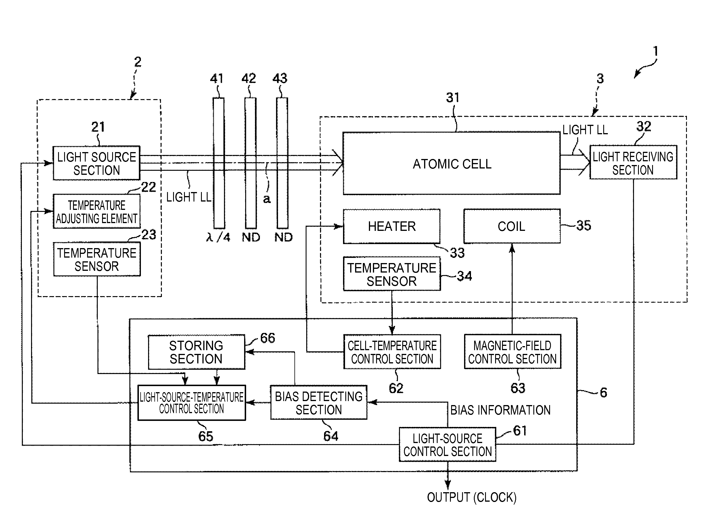
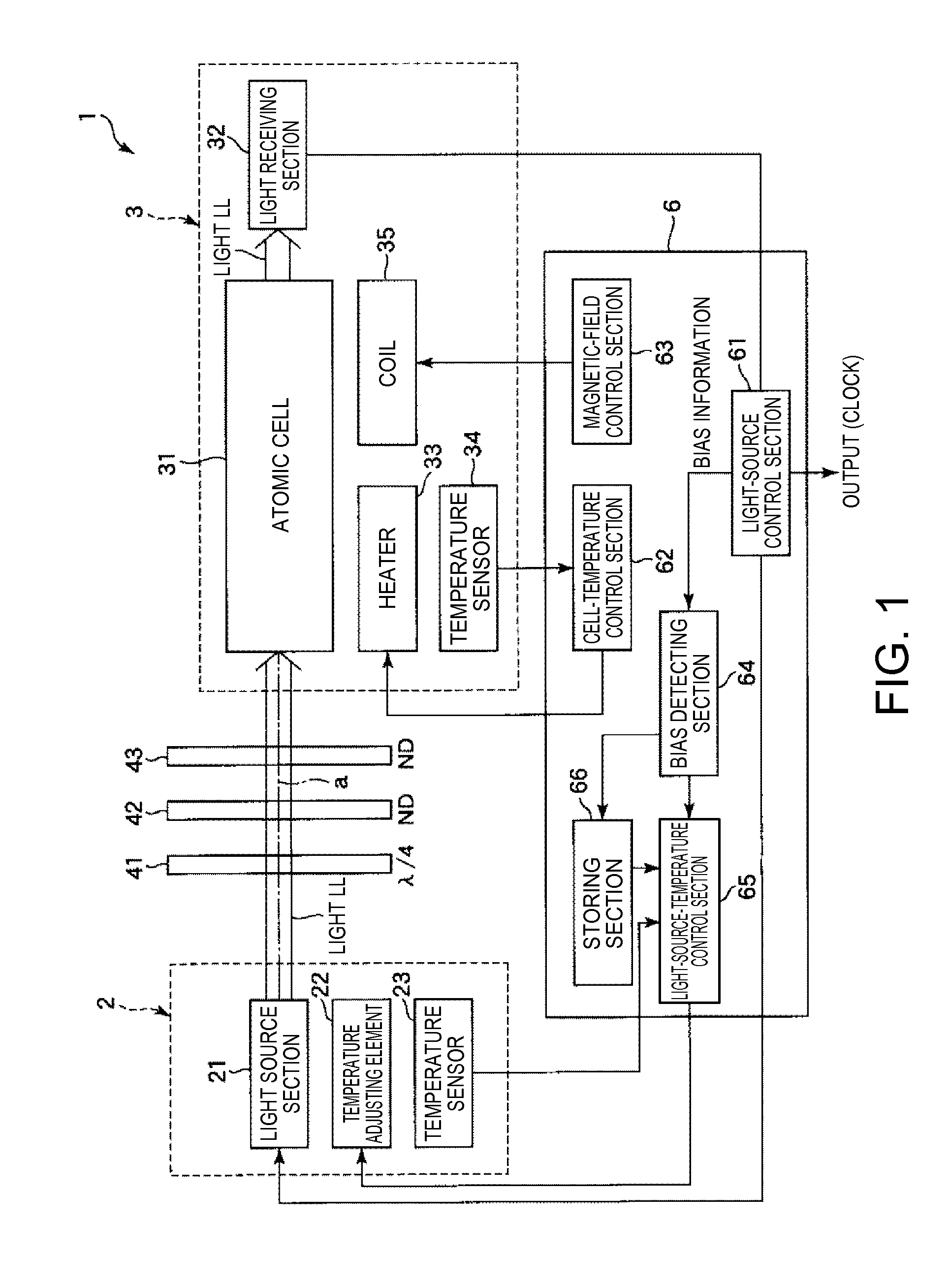
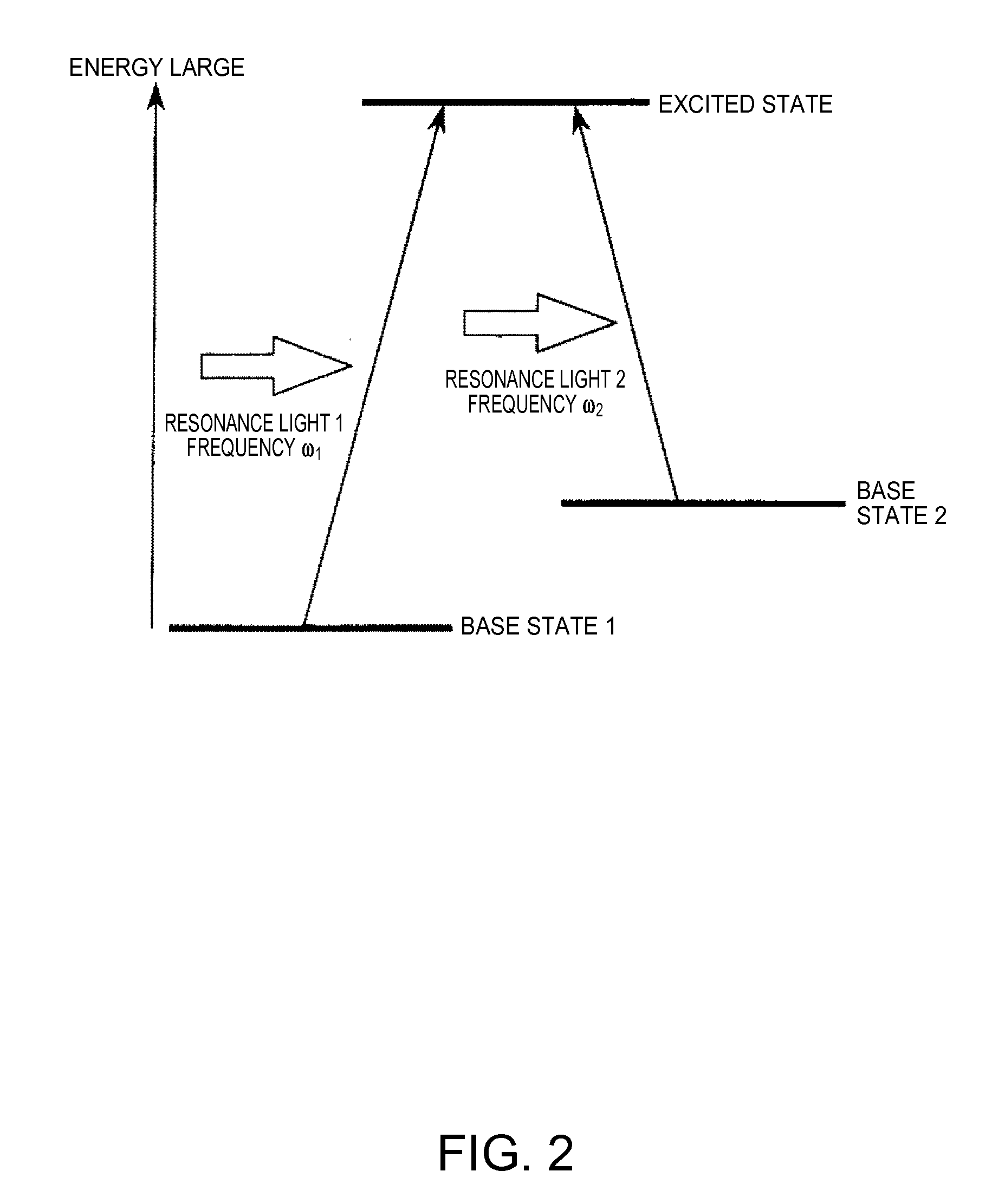
[0051]FIG. 1 is a schematic diagram showing the schematic configuration of an atomic oscillator (a quantum interference device) according to a first embodiment of the invention. FIG. 2 is a diagram for explaining an energy state of alkali metal. FIG. 3 is a graph showing a frequency difference between two lights emitted from a light source section and the intensity of light detected by a light receiving section.

[0052]An atomic oscillator 1 shown in FIG. 1 is an atomic oscillator utilizing a quantum interference effect.

[0053]The atomic oscillator 1 includes, as shown in FIG. 1, a light source side unit 2, a cell side unit 3, optical components 41, 42, and 43 provided between the units 2 and 3, and a control section 6 that controls the units 2 and 3.

[0054]The light source side unit 2 includes a light source section 21, a temperature adjusting element 22, and a temperature sensor 23. The cell side unit 3 includes an atomic cell 31, a light receiving section 32, a heater 33, a temperatu...

second embodiment

[0149]A second embodiment of the invention is explained below.

[0150]FIG. 9 is a schematic diagram showing the schematic configuration of an atomic oscillator (a quantum interference device) according to the second embodiment of the invention. FIG. 10 is a sectional view of a physical unit included in the atomic oscillator shown in FIG. 9.

[0151]This embodiment is the same as the first embodiment except that components on a light source side and components on an atomic cell side are integrated as one package and the configuration of the atomic oscillator is simplified according to the packaging of the components.

[0152]Note that, in the following explanation, concerning the second embodiment, differences from the first embodiment are mainly explained. Explanation concerning the similarities is omitted. In FIGS. 9 and 10, components same as the components in the first embodiment are denoted by the same reference numerals and signs.

[0153]The atomic oscillator 1 shown in FIG. 9 includes a...


PUM


Abstract

An atomic oscillator includes an atomic cell in which alkali metal atoms are encapsulated, a light source section configured to receive the supply of a bias and emit light including a resonance light pair for causing the alkali metal atoms to resonate, a temperature adjusting element configured to adjust the temperature of the light source section, a bias detecting section configured to detect information concerning the bias, and a light-source-temperature control section configured to control the temperature adjusting element using the information detected by the bias detecting section.

Description

CROSS REFERENCE[0001]This application claim benefit of Japanese Application No. 2014-223560, filed on Oct. 31, 2014. The disclosure of the prior application is hereby incorporated by reference herein in its entirety.BACKGROUND[0002]1. Technical Field[0003]The present invention relates to a quantum interference device, an atomic oscillator, an electronic device, and a moving object.[0004]2. Related Art[0005]As an oscillator having a highly accurate oscillation characteristic for a long term, there is known an atomic oscillator that oscillates on the basis of energy transition of atoms of alkali metal such as rubidium or cesium.[0006]In general, the operation principle of an atomic oscillator is roughly divided into a system utilizing a double resonance phenomenon by light and a microwave and a system utilizing a quantum interference effect (Coherent Population Trapping (CPT)) by two kinds of light having different wavelengths. However, in recent years, the atomic oscillator utilizing...

Claims


Application Information

Patent Timeline
IPC IPC(8): H03L7/26
CPCH03L7/26
Inventor MAKI, YOSHIYUKI
Owner SEIKO EPSON CORP
Why Eureka
Try Eureka