Liquid ejecting head and liquid ejecting apparatus

a liquid ejecting and liquid ejecting technology, which is applied in the direction of printing and inking apparatus, etc., can solve the problems of lowering the printing property of ink jet printers, prone to stagnation of ink in this angled corner, and prone to stay in the angled corner of bubbles generated inside the channel

Active Publication Date: 2016-08-04
SEIKO EPSON CORP
View PDF1 Cites 4 Cited by
  • Summary
  • Abstract
  • Description
  • Claims
  • Application Information

AI Technical Summary

Benefits of technology

[0022]According to the eighth aspect, the liquid ejecting apparatus reduces the risk that the liquid stays in the corner portion when the liquid that has flown along the channel in the first direction is curved in the second direction in t

Problems solved by technology

If the channel has an angled corner, the ink is prone to stagnate in this angled corner.
In addition, bubbles generated inside the channel are prone to stay in the angled corner.
If bubbles are generated inside a channel in an ink

Method used


Image

  • Liquid ejecting head and liquid ejecting apparatus
  • Liquid ejecting head and liquid ejecting apparatus
  • Liquid ejecting head and liquid ejecting apparatus

Examples


first embodiment

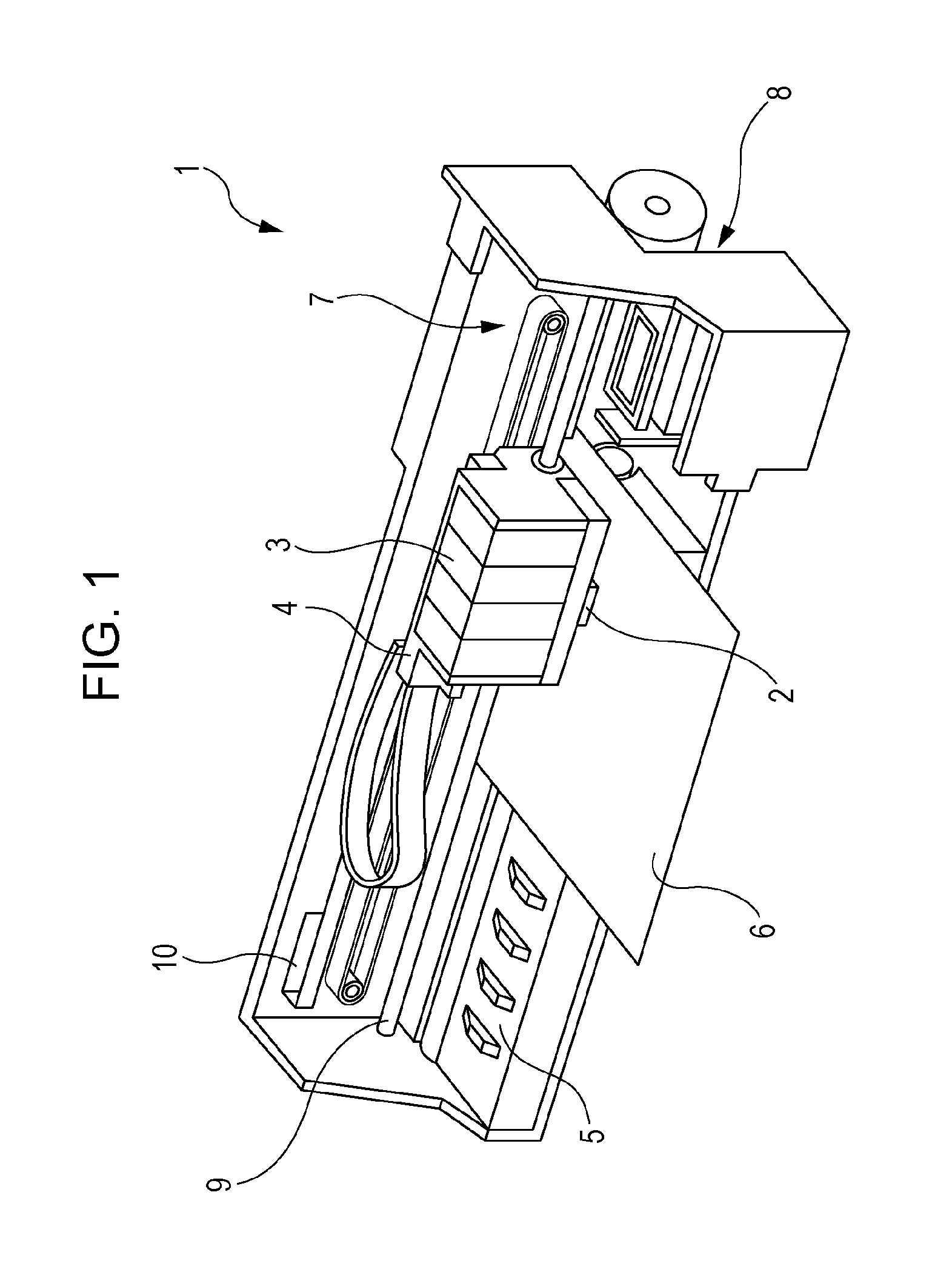
[0036]An ink jet recording apparatus 1 illustrated in FIG. 1 is an exemplary liquid ejecting apparatus. This ink jet recording apparatus 1 is referred to below as a printer 1.

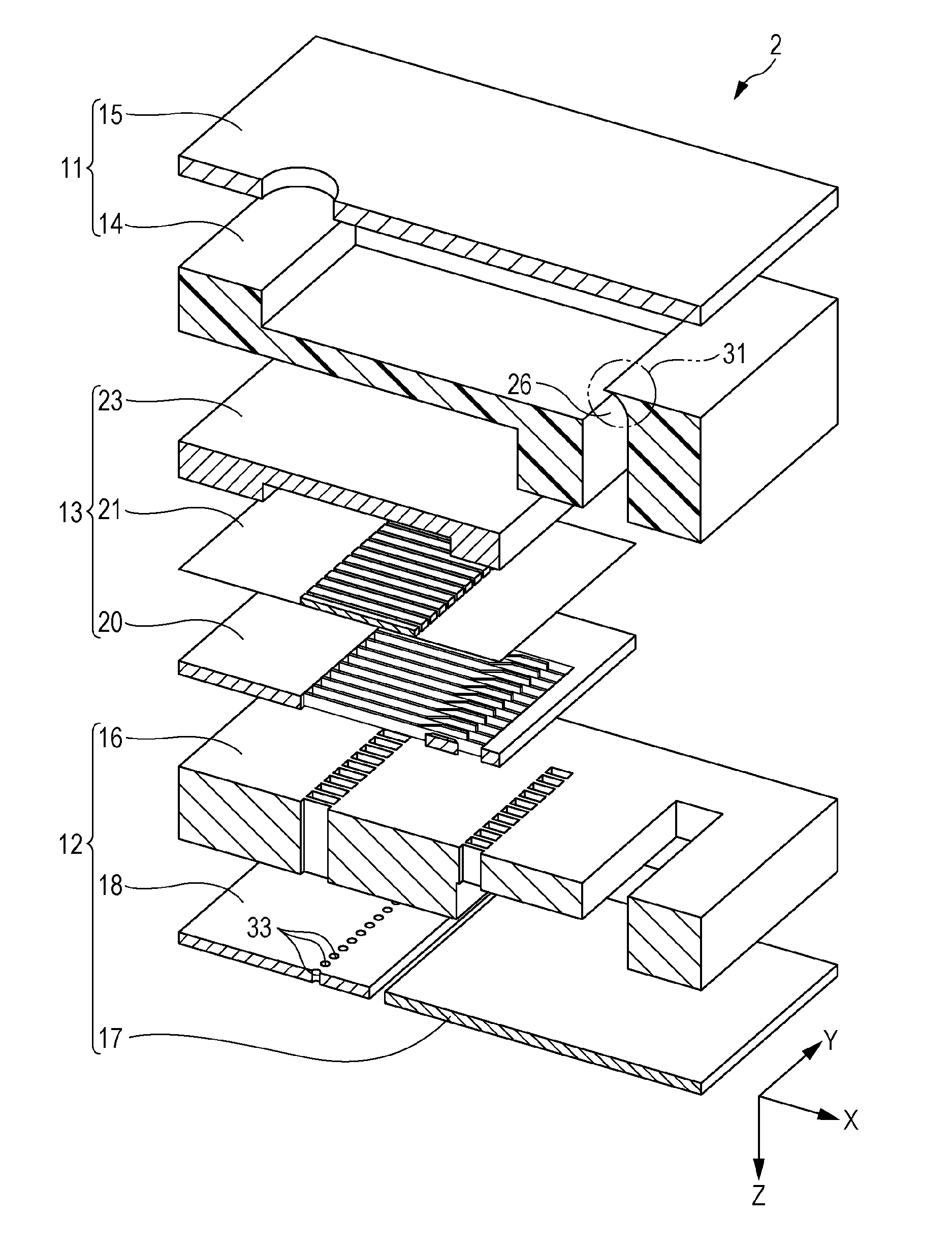
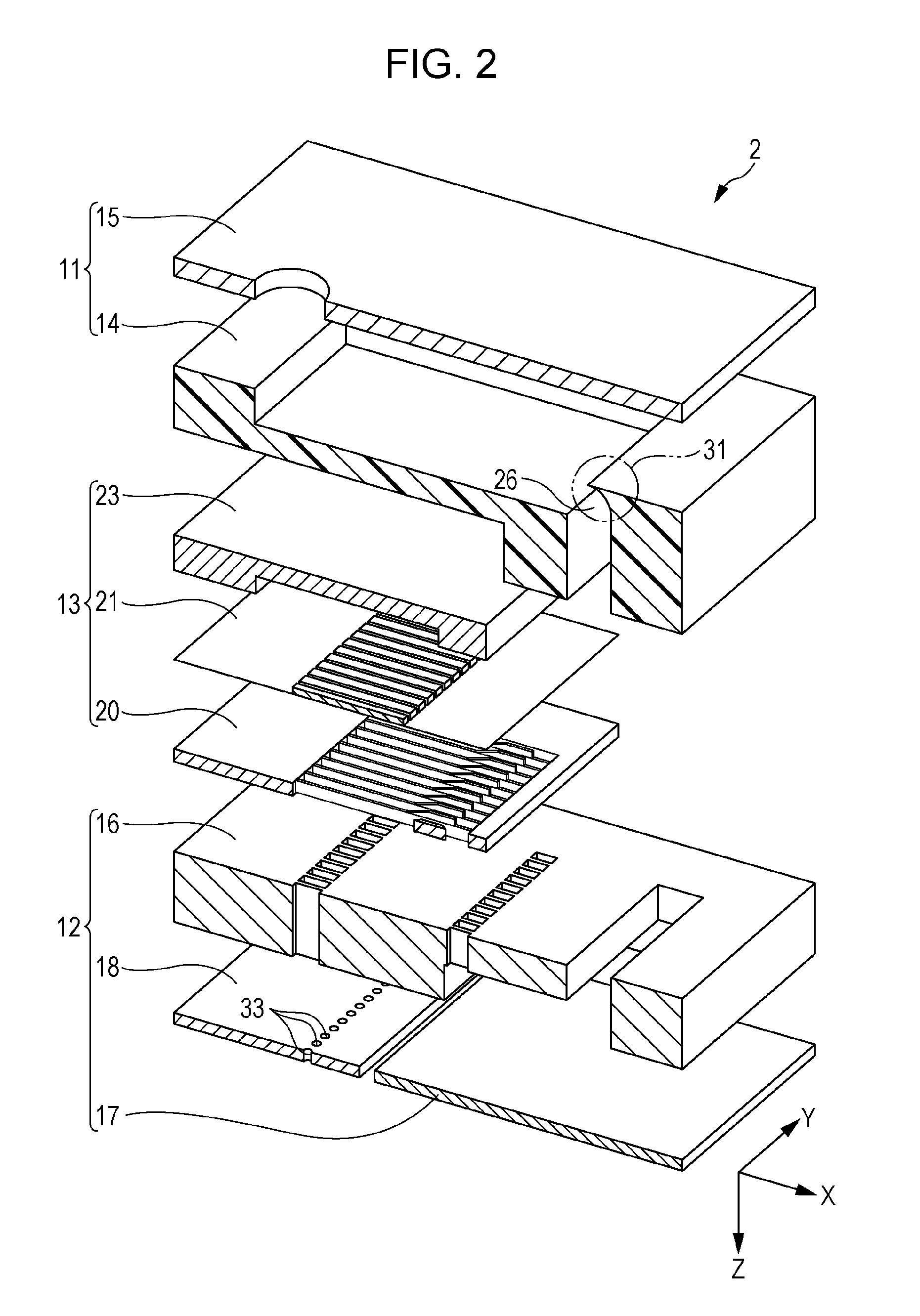
[0037]The printer 1 includes an ink jet recording head unit 2, which is an exemplary liquid ejecting head; the ink jet recording head unit 2 is referred to below as a head unit 2. The head unit 2 can eject liquid, more specifically ink, in droplet form. In the printer 1, the head unit 2 and ink cartridges 3 are mounted in a carriage 4. A platen 5 is disposed below the head unit 2. A carriage moving mechanism 7 moves the carriage 4 in sheet width directions of a recording sheet 6 that is a target on which ink ejected from nozzles 32 is to land. The sheet width directions are main-scanning directions in which the head unit 2 reciprocates. A sheet feeding mechanism 8 transports the recording sheet 6 in a sheet feeding direction, which is orthogonal to the sheet width directions. The sheet feeding direction is a su...

second embodiment

[0068]FIG. 8 is an enlarged sectional view of a curved section 26 in a second embodiment of the invention. With reference to FIG. 8, a head unit 2 in the second embodiment will be described. Constituent elements that are the same as in the first embodiment are denoted by the same reference characters and will not be described.

[0069]Referring to FIG. 8, the cover section 31 in the second embodiment has a wall 54 with a flat surface.

[0070]In addition to the effect of the first embodiment, the head unit 2 in the second embodiment produces an effect that it is possible to control the shape of the cover section 31 easily. Since the wall 54 in the cover section 31 in the first embodiment has a curved surface whose orientation gradually changes, it may be difficult to reliably form the wall 54 and measure this shape. In contrast, the wall 54 in the cover section 31 in the second embodiment has a flat surface, it is possible to form the wall 54 accurately in a manufacturing process and meas...

modification 1

[0072]FIG. 9 is an enlarged sectional view of a curved section 26 in modification 1 of the first and second embodiments. In the first and second embodiments, the wall 54 in the cover section 31 has a single surface as illustrated in FIG. 4; however, this configuration is exemplary. A head unit 2 in modification 1 will be described below. Constituent elements that are the same as in the first embodiment are denoted by the same reference characters and will not be described.

[0073]As illustrated in FIG. 9, a wall 54 in the cover section 31 in modification 1 has two surfaces. One of the surfaces of the wall 54 in the cover section 31 intersects the X direction, whereas the other one thereof intersects the Z direction. Examples of the combination of the surfaces include the combination of curved surfaces, the combination of flat surfaces, and the combination of curved and flat surfaces. The wall 54 in the cover section 31 may have three or more surfaces.

[0074]In addition to the effects o...


PUM


Abstract

A liquid ejecting head includes a plurality of stacked substrates that include a nozzle substrate having a nozzle from which liquid is ejected. A channel is formed in at least a part of the substrates and guides the liquid to the nozzle. The channel includes: a first channel that extends in an X direction intersecting a stacking direction in which the substrates are stacked; a curved section curved in a Z direction that intersects the X direction and contains a component of the stacking direction; and a second channel that extends from the curved section in the Z direction. A wall is formed in a corner portion inside the channel so as to intersect both the X and Z directions, and the corner portion is formed in the curved section between the inside walls of the first and second channels.

Description

BACKGROUND[0001]1. Technical Field[0002]The present invention relates to a liquid ejecting head and a liquid ejecting apparatus equipped with the liquid ejecting head.[0003]2. Related Art[0004]Ink jet printers are known examples of liquid ejecting apparatuses. A typical ink jet printer can print images on an arbitrary recording medium, such as a sheet of paper or cloth, by ejecting liquid onto the recording medium through a liquid ejecting head, more specifically ejecting ink through a recording head. Some recording heads known in the art have a structure in which a plurality of substrates are stacked on top of each other (e.g., Japanese Patent No. 4,258,668).[0005]In the recording head disclosed by Japanese Patent No. 4,258,668, a reservoir and a through-hole are formed in a protective substrate so as to cross each other; the protective substrate is one of a plurality of stacked substrates. This through-hole passes through the stacked substrates and reaches the reservoir while bein...

Claims


Application Information

Patent Timeline
IPC IPC(8): B41J2/14
CPCB41J2/1433B41J2002/14241B41J2002/14362B41J2202/11B41J2/14233B41J2/14274
Inventor TOMIMATSU, SHINGOWATANABE, SHUNSUKE
Owner SEIKO EPSON CORP
Why Eureka
Try Eureka