Eureka AIR delivers breakthrough ideas for toughest innovation challenges, trusted by R&D personnel around the world.

Apparatus and method for controlling electronic parking brake

Active Publication Date: 2016-08-04
HL MANDO CORP
View PDF4 Cites 2 Cited by
  • Summary
  • Abstract
  • Description
  • Claims
  • Application Information

AI Technical Summary

Benefits of technology

The present invention relates to an apparatus and method for controlling an electronic parking brake. The technical effects of this invention include improving parking convenience, enabling a driver to recognize an unstable parking state and take a fast initial countermeasure, recognizing a stable future parking state and further improving the reliability of parking, and detecting the current wheel pulse counting signals in real time even when starting of a vehicle is turned off.

Problems solved by technology

However, in the electronic parking brake according to the related art, when the driver does not quickly recognize a state in which a vehicle rolls in a rear direction, a parking state is not smoothly formed after parking has been performed such that there is a limitation in improvements in conveniences of parking.

Method used


Image

  • Apparatus and method for controlling electronic parking brake
  • Apparatus and method for controlling electronic parking brake
  • Apparatus and method for controlling electronic parking brake

Examples


first embodiment

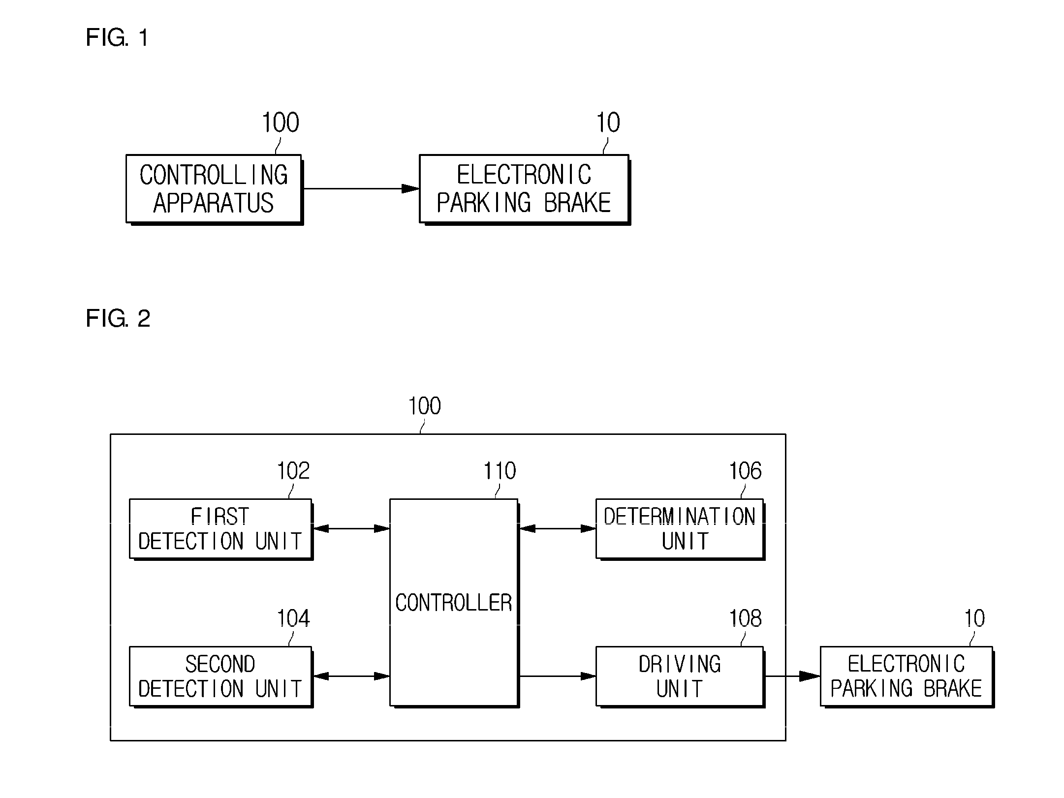
[0049]FIG. 1 is a block diagram illustrating a state in which an apparatus for controlling an electronic parking brake in accordance with the present invention is connected to the electronic parking brake, and FIG. 2 is a block diagram illustrating the apparatus illustrated in FIG. 1, in one example.

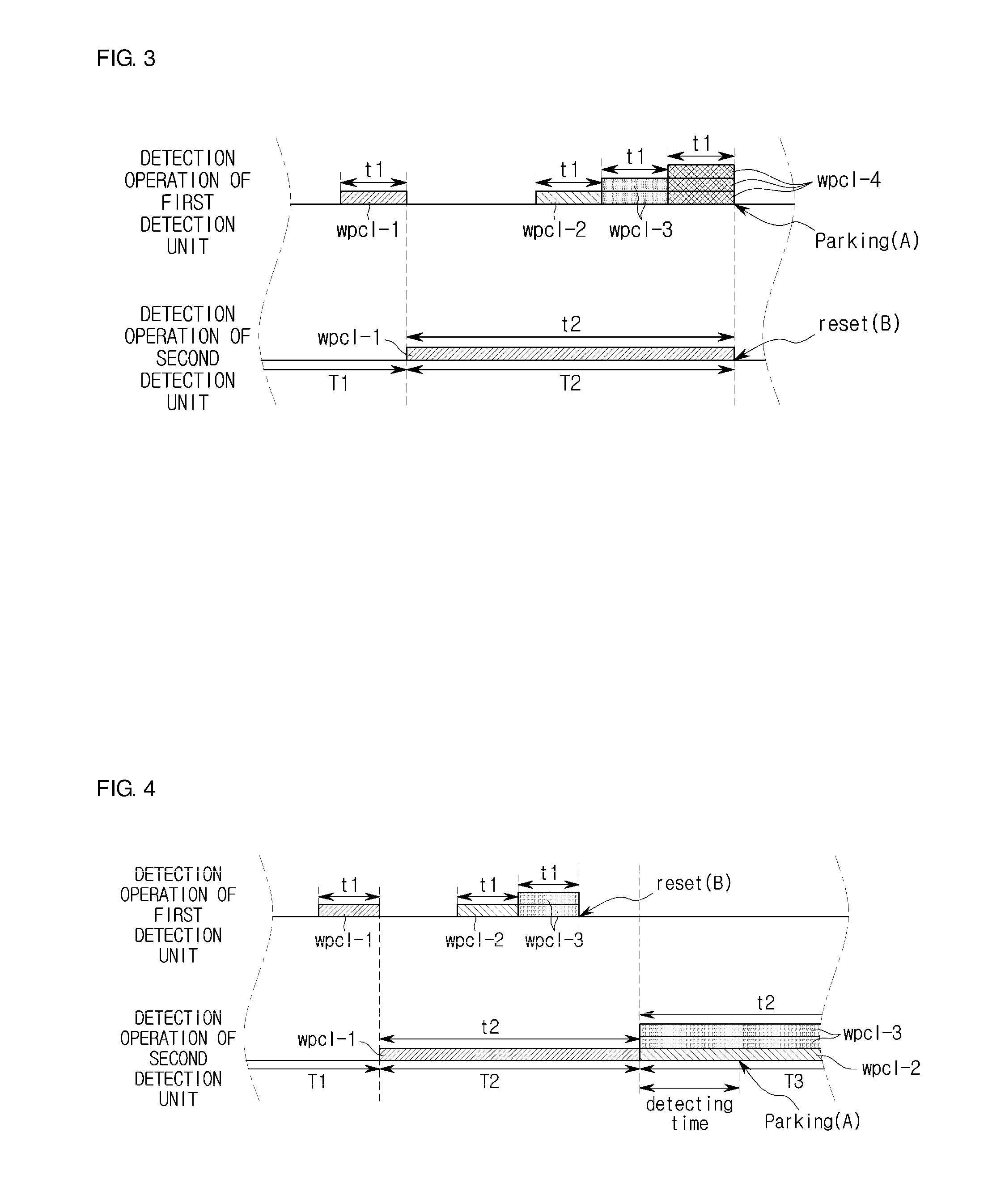
[0050]FIG. 3 is a view illustrating a state in which a parking operation caused by a detection operation performed by a first detection unit illustrated in FIG. 2 is re-clamped, and

[0051]FIG. 4 is a view illustrating a state in which a parking operation caused by a detection operation performed by a second detection unit illustrated in FIG. 2 is re-clamped.

[0052]Referring to FIGS. 1 through 4, an apparatus 100 for controlling an electronic parking brake 10 in accordance with a first embodiment of the present invention includes a first detection unit 102, a second detection unit 104, a determination unit 106, a driving unit 108, and a controller 110.

[0053]After clamping a parking operatio...

second embodiment

[0097]FIG. 6 is a block diagram illustrating a state in which an apparatus for controlling an electronic parking brake in accordance with the present invention is connected to the electronic parking brake and communicates with a portable mobile terminal device, and FIG. 7 is a block diagram illustrating the apparatus illustrated in FIG. 6, in one example.

[0098]Referring to FIGS. 6 and 7, an apparatus 600 for controlling an electronic parking brake 10 in accordance with a second embodiment of the present invention includes a first detection unit 602, a second detection unit 604, a determination unit 606, a driving unit 608, and a controller 610, like in the apparatus (100 of FIGS. 1 and 2) for controlling the electronic parking brake (10 of FIGS. 1 and 2) in accordance with the first embodiment of the present invention.

[0099]Since functions of the first detection unit 602, the second detection unit 604, the determination unit 606, the driving unit 608, and the controller 610 of the a...


PUM


Abstract

Disclosed herein are an apparatus and method for controlling an electronic parking brake. The apparatus for controlling the electronic parking brake includes: a first detection unit that detects current wheel pulse counting signals when a vehicle rolls at a predetermined time interval for a predetermined time period after a parking operation for parking is clamped; a second detection unit that continuously receives the detected current wheel pulse counting signals at a predetermined time interval for a next time period after the predetermined time period and detects the continuously-cumulated current wheel pulse cumulative counting signals; a determination unit that determines whether the detected current wheel pulse counting signals are predetermined target wheel pulse counting signals or determines whether the detected current wheel pulse cumulative counting signals are predetermined target wheel pulse cumulative counting signals; a driving unit that drives the electronic parking brake so as to re-clamp the parking operation if it is determined that the current wheel pulse counting signals are the target wheel pulse counting signals or the current wheel pulse cumulative counting signals are the target wheel pulse cumulative counting signals; and a controller that transmits a first detection instruction to the first detection unit, transmits a second detection instruction to the second detection unit, transmits a determination instruction to the determination unit and transmits a driving instruction to the driving unit.

Description

CROSS-REFERENCE TO RELATED APPLICATION[0001]This application claims the benefit of Korean Patent Application No. 2015-0016444, filed on Feb. 3, 2015 in the Korean Intellectual Property Office, the disclosure of which is incorporated herein by reference.BACKGROUND[0002]1. Field[0003]Embodiments of the present invention relate to an apparatus and method for controlling an electronic parking brake.[0004]2. Description of the Related Art[0005]In general, an electronic parking brake according to the related art has been provided in such a way that, when a driver turns off starting using a driver-friendly automatic brake device, the brake operates automatically and when the driver steps on an accelerator while turning on starting, the brake is automatically released such that conveniences of parking are improved.[0006]However, in the electronic parking brake according to the related art, when the driver does not quickly recognize a state in which a vehicle rolls in a rear direction, a par...

Claims


Application Information

Patent Timeline
IPC IPC(8): B60T1/00B60T13/74B60T7/12B60T8/171
CPCB60T1/005B60T7/12B60T13/746B60T8/171B60T8/17B60W30/06B60T13/74B60T7/122B60W10/192
Inventor NO, SU-HWAN
Owner HL MANDO CORP
Why Eureka
Eureka Blog
Learn More