Coupling system of removable compartment for applicances

a technology of a removable compartment and a coupling system, which is applied in the field of coupling systems, can solve the problems of inconvenient use for users, high torque to promote the rotation of the stirrer, and the coupling to the upper end of the stirrer does not appear very suitable, so as to avoid the increase of the electricity consumption of the apparatus, the effect of convenient use for users

Active Publication Date: 2016-08-04
WHIRPOOL SA
View PDF9 Cites 22 Cited by
  • Summary
  • Abstract
  • Description
  • Claims
  • Application Information

AI Technical Summary

Benefits of technology

[0010]Thus, it is one of the objectives of the present invention to provide for a coupling system of removable compartment for appliances that is easy to use by the user.
[0011]Another among the objectives of the present invention is to provide for a coupling system that does not require the use of any additional device or component to be effected.
[0012]It is still one of the objectives of the invention to provide for a coupling system that does not interfere in the operation of the appliance stirrer, so as not to incur increased torque to drive the stirrer and, thus, does not raise the electricity consumption of the apparatus.
[0013]Moreover, one objective of the invention is to provide a coupling form that allows the frequent insertion and removal of the removable internal compartment without this fact may lead, in the short or medium term, to wear able to compromise the sealing and insulation between the washing compartments.
[0014]Finally, it is also an objective of the invention to disclose a coupling system of additional washing compartment with a significantly low cost of production and operation, providing the user with the possibility to have an additional function in the equipment thereof without incurring significant increase in the costs of the apparatus.

Problems solved by technology

However, it occurs that the existence of only one washing room cause inconvenience to the user, since the white and / or very light clothes cannot be washed with colored clothes at risk of acquiring stains that prevent the their reuse, so that, no matter how small the load of clothes to be washed is, two complete washing cycles are needed to process all the material to be sanitized.
However, the coupling to the upper end of the stirrer does not appear very suitable because in addition to keeping the additional washing room only partially arranged within the washing basket, it also has the disadvantage of requiring a higher torque to promote rotation of the stirrer, once it transfers to the stirrer all the weight of the clothes load existing in the inside thereof.
Furthermore, mainly during the centrifugation step, both the stirrer and the small washing compartment undergo a very large moment, so that friction between the parts may occur and thus cause wear of the stirrer as well as damage to the axis thereof.
Document U.S. Pat. No. 4,637,231 also discloses the use of an additional washing basket coupled to the stirrer axis, thus incurring the same drawback described in the preceding paragraph.
Thus, it is a solution that requires the use of additional components—in the case, said flange—to provide coupling and fluid seal between the baskets, so that if it occurs a problem in this flange or a possible inappropriate coupling by the user, the fluid communication may occur between the baskets and thus cause stains in the light-colored clothes and inconveniences to the user.
It is noted, therefore, that the current state of the art lacks solutions allowing a safe, efficient and practical coupling of an additional washing basket and fluidly independent with the conventional washing basket of the clothes washing machines of the current state of the art.

Method used


Image

  • Coupling system of removable compartment for applicances
  • Coupling system of removable compartment for applicances
  • Coupling system of removable compartment for applicances

Examples


Embodiment Construction

[0028]The object of the present invention will be described and explained in more details based on the accompanying drawings, which have merely exemplary and non-limiting character, since adaptations and modifications may be made without thereby escaping from the scope of protection claimed.

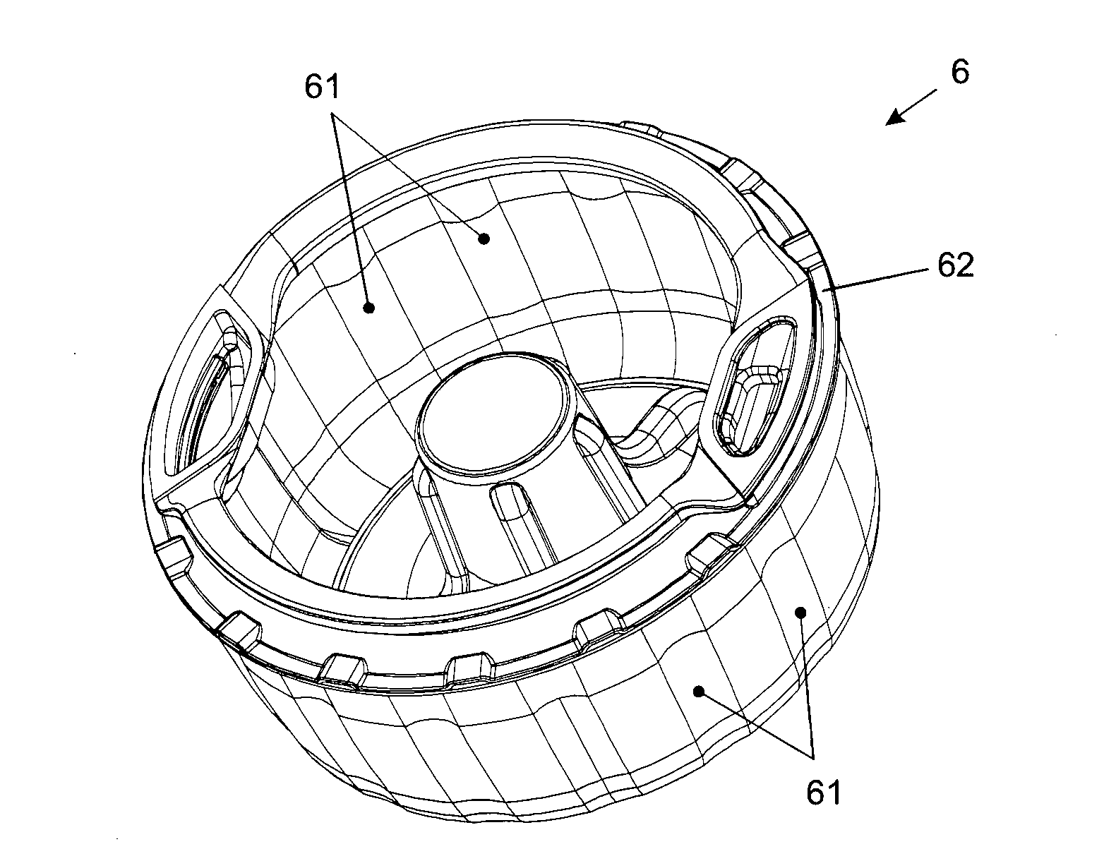
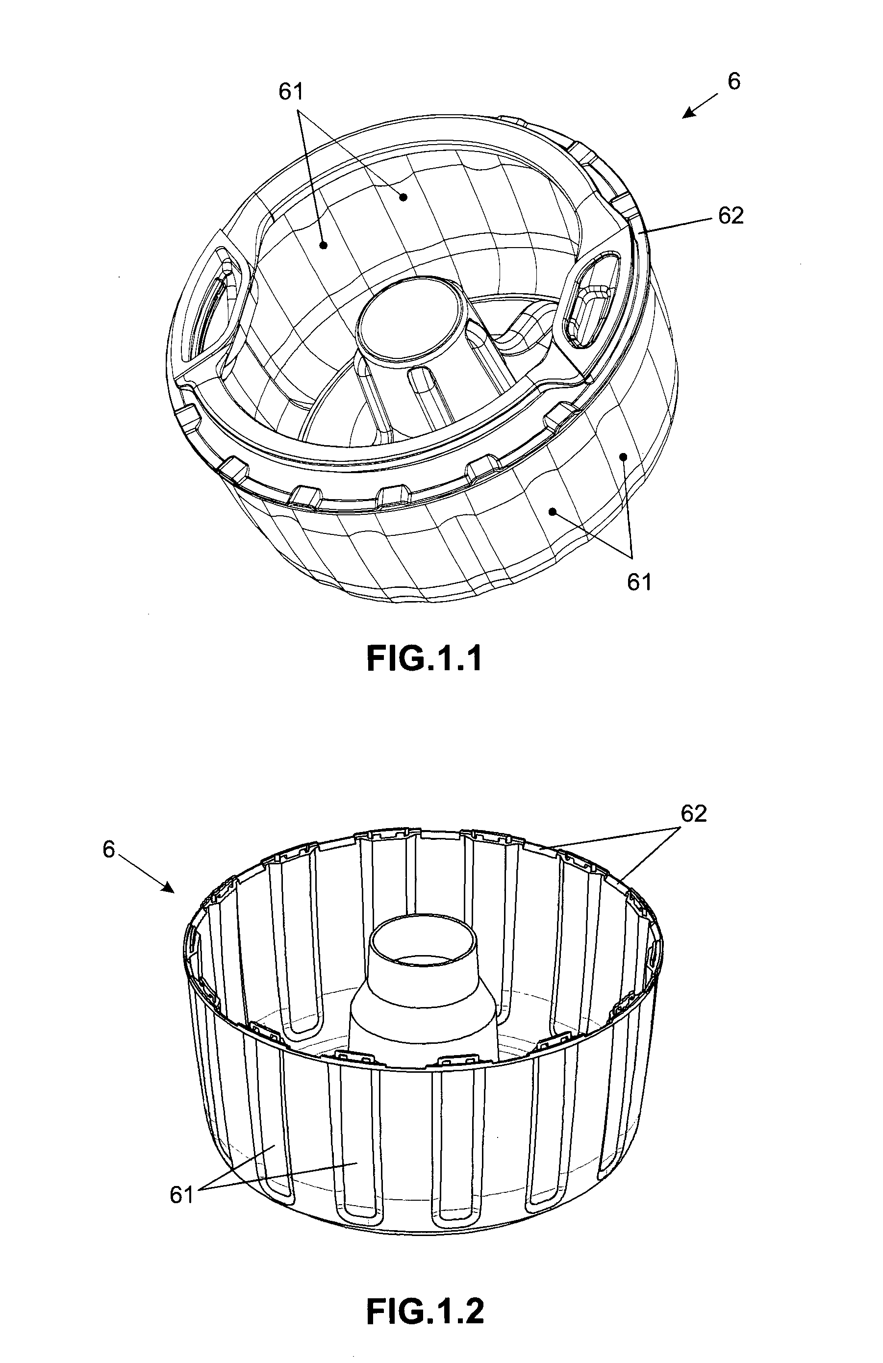
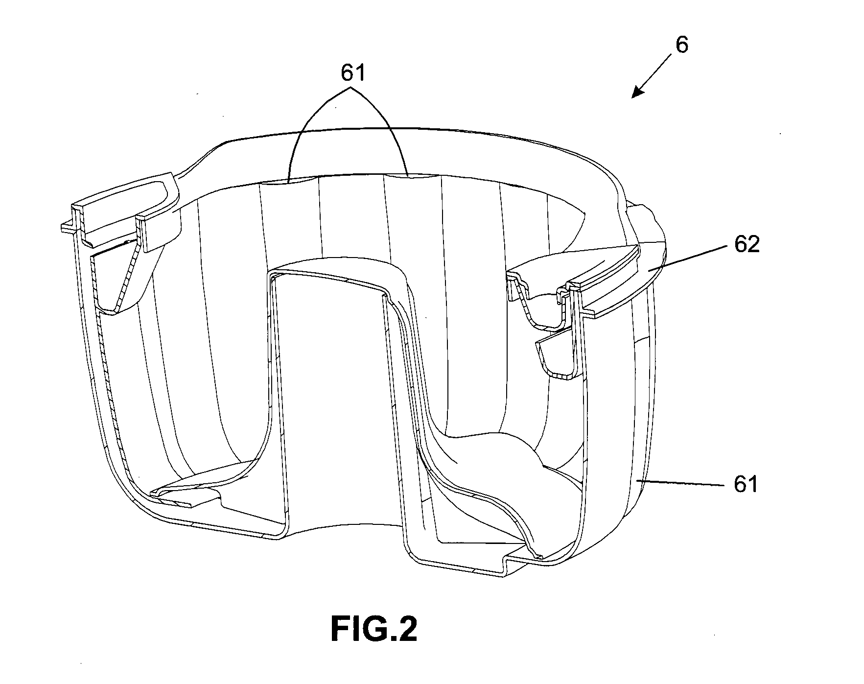
[0029]The present invention relates to a coupling system of compartments intended to the use in clothes washing machine 1 and more specifically in clothes washing machines of vertical axis / stirrer 7 with access cover located on the upper surface thereof. So basically such appliances comprising a cabinet 2 inside which it is located a generally cylindrical fixed tank 3 which stores the water during the soaking and washing process of the load of clothes to be processed, wherein at the center of the fixed tank 3 it is located the stirrer element 7 internally containing, the rotor axis of the appliance motor (not shown).

[0030]In an inner and concentric manner relative to the fixed tank 3, it is coupl...


PUM


Abstract

The present invention relates to a coupling system intended more specifically to the fitting and attaching of additional and removable internal baskets defining isolated washing rooms in clothes washing machines. Such a system is intended more particularly to clothes washing machines (1) comprising a cabinet (2) within which it is located a fixed tank (3) with which cooperate a washing basket (4), a balancing device (5), a removable washing compartment (6) and an stirrer element (7), characterized by the fact that the balancing device (5) comprises at least one surface comprising a plurality of coupling members (51) and the removable washing compartment (6) cooperates with the balancing device (5), wherein said removable washing compartment (6) comprises at least one surface comprising a plurality of coupling elements (61) cooperating with the elements coupling (51) of the balancing device (5).

Description

FIELD OF THE INVENTION[0001]The present invention relates to a coupling system intended, more specifically, to the fitting and attaching of additional and removable internal baskets that define isolated washing rooms, in clothes washing machines. Thus, the object of the present invention is to provide a system enabling that the coupling of such elements is in a simpler and more practical manner than those obtained through the use of similar known ones.BACKGROUND OF THE INVENTION[0002]As is generally known, the clothes washing machines conventionally have a unique washing room defined by mobile basket arranged inside a fixed tank, wherein such mobile basket is usually perforated to allow drainage and spin of the clothes during the washing process.[0003]In the more specific case of the clothes washing machines of vertical axis / upper opening, such mobile baskets are centrally coupled to the stirrer and provided, in the upper edge, of a hydro-balancer ring which keeps the equipment in b...

Claims


Application Information

Patent Timeline
Patent Type & Authority Applications(United States)
IPC IPC(8): D06F1/12
CPCD06F37/16D06F1/12D06F37/245D06F37/12D06F95/002
Inventor RAMASCO, BRUNO T.MANZ, GUILHERME
Owner WHIRPOOL SA
Why Eureka
Try Eureka