Rifle scope targeting display adapter mount

a display adapter and scope technology, applied in the direction of sighting devices, machine supports, weapons, etc., can solve the problems of noise generation, distraction, and the like of the rifle on the rifle suppor

Active Publication Date: 2016-08-04
CUBIC CORPORATION
View PDF6 Cites 29 Cited by
  • Summary
  • Abstract
  • Description
  • Claims
  • Application Information

AI Technical Summary

Problems solved by technology

However, this process requires the sniper to remove his / her hands from the firing position, which may cause the rifle to shift on the rifle support.
Communicating targeting information verbally between the spotter and the sniper can also generate noise and distractions that can give away the sniper's position.

Method used


Image

  • Rifle scope targeting display adapter mount
  • Rifle scope targeting display adapter mount
  • Rifle scope targeting display adapter mount

Examples


Embodiment Construction

[0045]Several illustrative embodiments of a rifle scope display adapter will now be described with respect to the accompanying drawings, which form a part of this disclosure. While particular rifle scope display adapter implementations and embodiments are described below, other embodiments and alternative designs may be made without departing from the scope of the disclosure or the spirit of the appended claims.

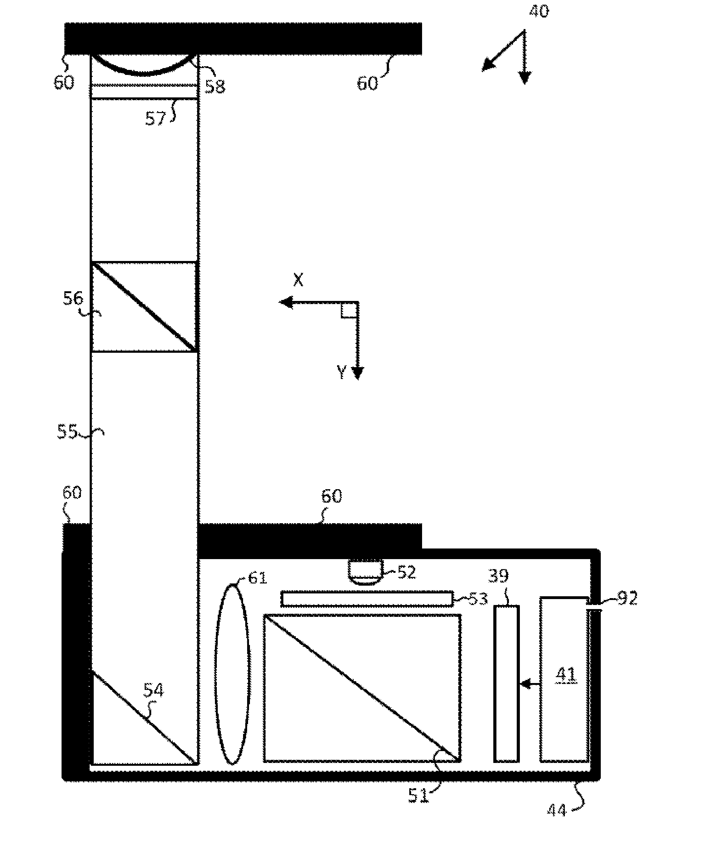
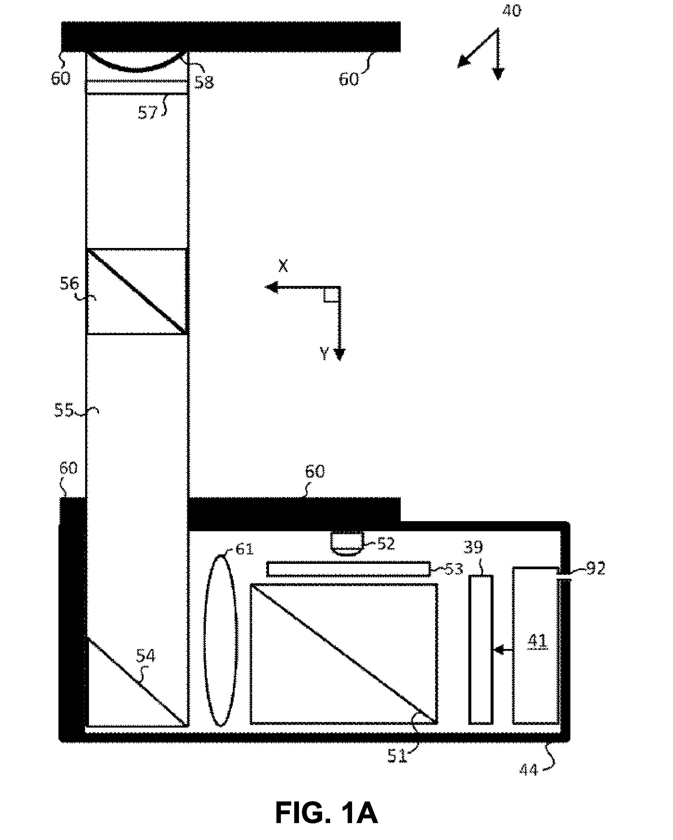
[0046]According to some embodiments, a lightweight, compact rifle scope display adapter can be configured to be securely affixed to a rifle scope in front of the scope's objective lens. When attached to a rifle scope, the “rifle scope display adapter” (hereinafter also referred to interchangeably as a “display adapter” and / or an “adapter”) can be operated to supplement the rifle scope view of the target by displaying aim point and / or trajectory information computed by a ballistic computer for a selected target. Specifically, the rifle scope display adapter can provide aim poi...


PUM


Abstract

This disclosure describes a compact and lightweight rifle scope display adapter configured to be affixed in front of the objective lens of a rifle scope. The display adapter includes a receptacle that enables the adapter to be electrically connected to a ballistic computer, rangefinder or other targeting mechanism. The display adapter is configured to receive aimpoint information and project illuminated symbology that is brought into focus by the rifle scope optics in such a way that the symbology appears to overlay an image of a scene on which the rifle scope is focused. The adapter includes a mounting assembly that provides two attachment mechanisms. A first ring of the RDA can be screwed into the threads on the interior surface of the scope. Additionally, the scope can be inserted into a second ring of the RDA and provides compressive, radial pressure against the outside surface of the scope.

Description

CROSS-REFERENCES TO RELATED APPLICATIONS[0001]The present application claims the benefit under 35 USC 119(e) of U.S. Provisional Application No. 62 / 144,218, filed on Apr. 7, 2015, entitled “MULTI-USE RIFLE SCOPE PROJECTED DISPLAY MOUNTING TECHNIQUE,” which is incorporated herein by reference. The present application is also a continuation-in-part of U.S. patent application Ser. No. 15 / 079,851, filed on Mar. 24, 2016, entitled “RIFLE SCOPE TARGETING DISPLAY ADAPTER,” which is incorporated herein by reference.[0002]U.S. patent application Ser. No. 15 / 079,851 claims the benefit under 35 USC 119(e) of the following U.S. Provisional Applications: U.S. Provisional Application No. 62 / 137,585, filed on Mar. 24, 2015, entitled “SMART COMPACT RIFLE SCOPE DISPLAY ADAPTER (RDA)”; U.S. Provisional Application No. 62 / 138,893, filed on Mar. 26, 2015, entitled “RIFLE SCOPE WITH INTEGRATED TARGETING DISPLAY”; and U.S. Provisional Application No. 62 / 144,218, filed on Apr. 7, 2015, entitled “MULTI-USE...

Claims


Application Information

Patent Timeline
Patent Type & Authority Applications(United States)
IPC IPC(8): F41G11/00F16M13/02F41G1/38
CPCF41G11/00F16M2200/022F16M13/02F41G1/38
Inventor MARYFIELD, TONYDADKHAH, MAHYARCUGNETTI, CHRISTIAN
Owner CUBIC CORPORATION
Why Eureka
Try Eureka