180 degree hybrid coupler and dual-linearly polarized antenna feed network

a hybrid coupler and dual-linear polarized technology, applied in coupling devices, basic electric elements, waveguide type devices, etc., can solve the problems of increasing the size of a host device, limiting the number of hybrid couplers used, and limiting the number of host devices and/or associated devices that can be arranged

Active Publication Date: 2016-08-04
TYCO ELECTRONICS LOGISTICS AG (CH)
View PDF0 Cites 5 Cited by
  • Summary
  • Abstract
  • Description
  • Claims
  • Application Information

AI Technical Summary

Benefits of technology

[0009]In an embodiment, a 180° hybrid coupler includes first and second inputs, first and second outputs, first, second, and third coupled-line couplers each being defined by at least one ground conductor and only first and second signal conductors, and an electrically short transmission line connected between the first coupled-line coupler and the second coupled-line coupler. The first input is connected to the first signal conductor of the first coupled-line coupler at a first end of the first coupled-line coupler. The second signal conductor of the first coupled-line coupler is terminated to ground at the first end of the first coupled-line coupler. The second signal conductor of the first coupled-line coupler is connected to the first output at a second end of the first coupled-line coupler. The second signal conductor of the first coupled-line coupler is connected to the first signal conductor of the third coupled-line coupler at the second end of the first coupled-line coupler and at a first end of the third coupled-line coupler. The transmission line is connected to the first signal conductor of the first coupled-line coupler at the second end of the first coupled-line coupler. Th...

Problems solved by technology

For example, at least some known 180° hybrid couplers are larger than desired, which may increase the size of a host device, limit the number of hybrid couplers used in a host device (e.g., a feed network) and/or with an associated device (e.g., an antenna), limit the number of host devices and/or associated devices that can be arranged in an available space, and/or the like.
Moreover, at least some known 180° hybrid couplers are difficult to manufacture, which may increase cost and/or limit utility of such hybrid couplers.
Another disadvantage of at least some known 180° hybrid couplers is a relatively narrow bandwidth.
Moreover, at least some known 180° hybrid couplers may not operate at relatively high frequencies (e.g., frequencies above one Gigahertz and/or the like), which may prevent a host device and/or an associated device from operating at such frequencies...

Method used


Image

  • 180 degree hybrid coupler and dual-linearly polarized antenna feed network
  • 180 degree hybrid coupler and dual-linearly polarized antenna feed network
  • 180 degree hybrid coupler and dual-linearly polarized antenna feed network

Examples


Embodiment Construction

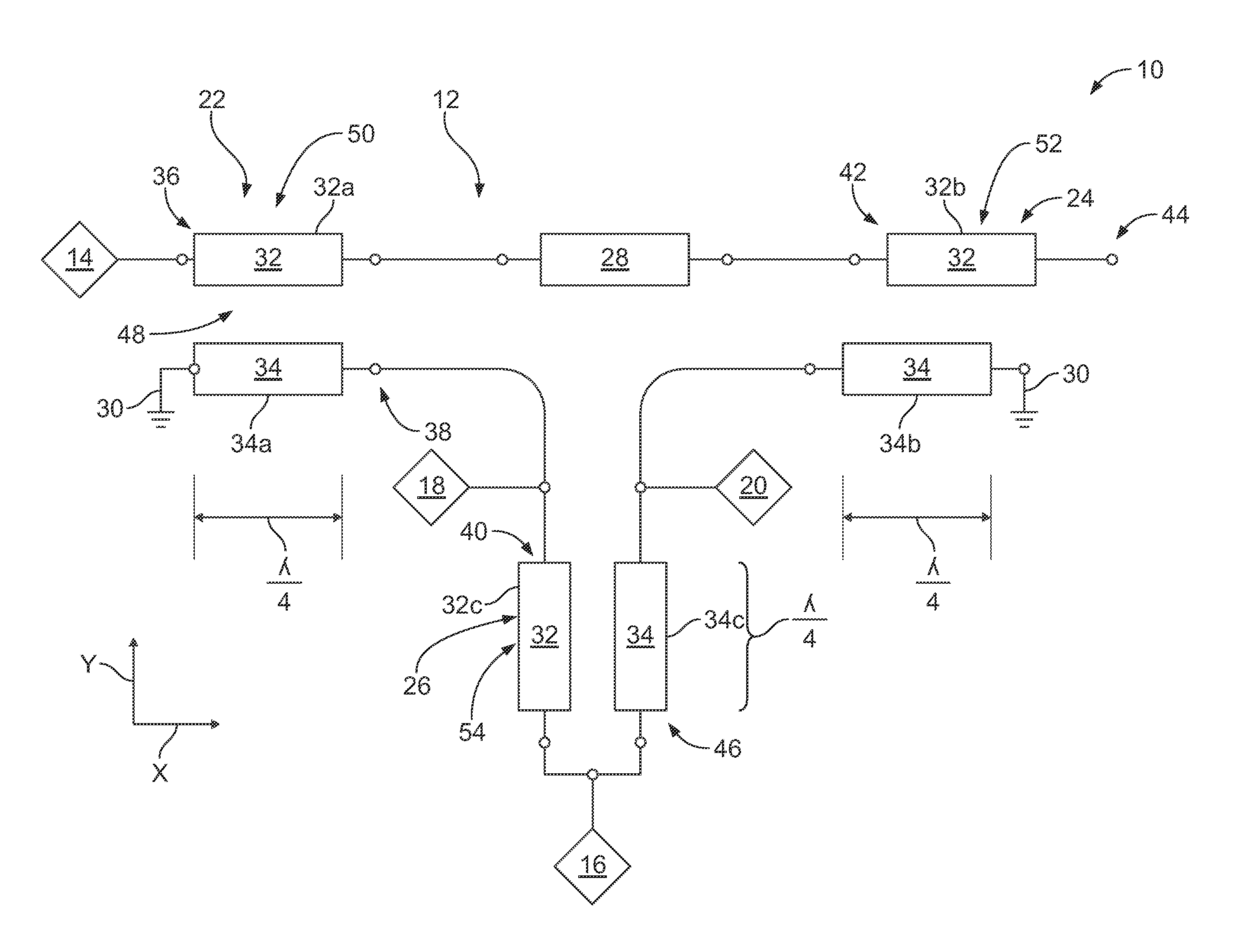
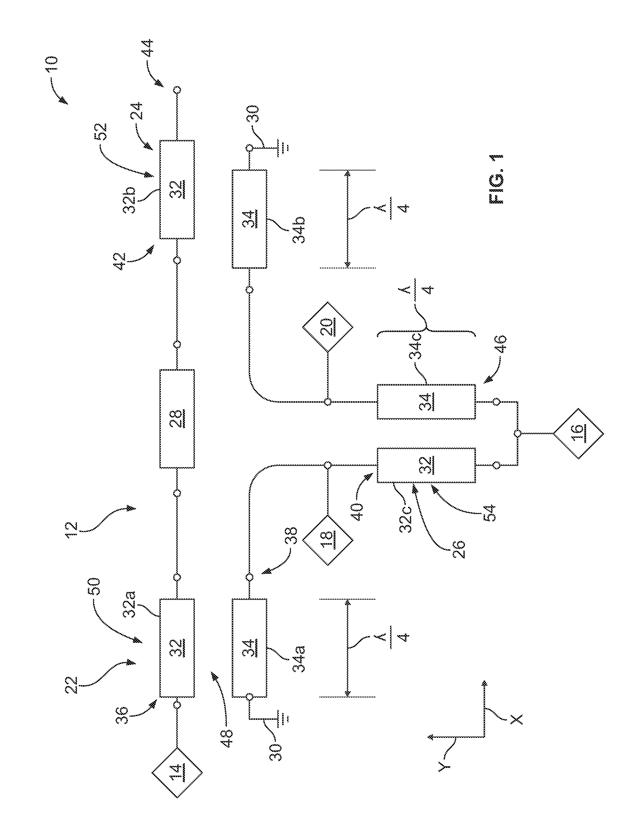
[0020]FIG. 1 is a schematic view of an embodiment of a 180° coupled-line hybrid coupler 10. The 180° hybrid coupler 10 includes a circuit 12 having two inputs 14 and 16 and two outputs 18 and 20. The circuit 12 includes three coupled-line couplers 22, 24, and 26 connected between the inputs 14 and 16 and the outputs 18 and 20. The circuit 12 also includes a transmission line 28 directly connected between two of the three coupled-line couplers 22, 24, and 26. As will be described below, each of the three coupled-line couplers 22, 24, and 26 is defined by one or more ground conductors 30 and only two signal conductors 32 and 34. Moreover, and as will be described below, the transmission line 28 may have an electrically short (i.e., small) length. In some embodiments, the transmission line 28 has an electrical length of zero.

[0021]The inputs 14 and 16 will be referred to herein as first and second inputs 14 and 16, respectively. The outputs 18 and 20 will be referred to herein as first...


PUM


Abstract

A 180° hybrid coupler includes three coupled-line couplers connected between two inputs and two outputs. Each of the three coupled-line couplers is defined by at least one ground conductor and only two signal conductors.

Description

BACKGROUND[0001]The subject matter disclosed herein relates generally to 180° hybrid couplers and dual-linearly polarized antenna feed networks for four-port antennas.[0002]Hybrid couplers (also referred to as “Hybrid junctions”) are four-port circuits that combine two input signals to create two output signals. Generally, the two output signals from a hybrid coupler are approximately equal in amplitude. Hybrid couplers are named according to the phase difference between their two output ports, with 0°, 90°, and 180° hybrid couplers being the most common configurations. Hybrid couplers are used in a wide variety of applications such as, but not limited to, feed networks, balanced mixers, impedance measuring devices, modulators, phase adjusters, tuners, and comparators.[0003]Known 180° hybrid couplers are not without disadvantages. For example, at least some known 180° hybrid couplers are larger than desired, which may increase the size of a host device, limit the number of hybrid co...

Claims


Application Information

Patent Timeline
IPC IPC(8): H01P5/12
CPCH01P5/184H01P5/12H01P5/185
Inventor FASENFEST, KATHLEEN
Owner TYCO ELECTRONICS LOGISTICS AG (CH)
Why Eureka
Try Eureka