Wideband dual-linear polarization bipole antenna array
A technology of dipole antenna and double-wire polarization, which is applied in the direction of antenna unit combination with different polarization directions, resonant antenna, mid-position feed between antenna endpoints, etc., which can solve the problem that the dipole unit form cannot be applied, Complicated feed network design, limited unit structure, etc., to achieve good polarization isolation performance, small mutual coupling, and good unit applicability
- Summary
- Abstract
- Description
- Claims
- Application Information
AI Technical Summary
Problems solved by technology
Method used
Image
Examples
Embodiment 1
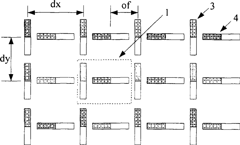
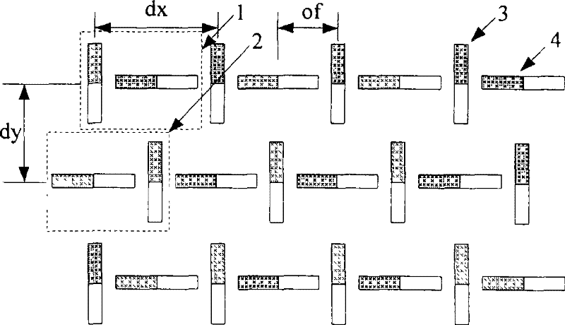
[0035] see figure 1 and figure 2 , each radiating element 1 in the figure is composed of a vertically polarized dipole antenna unit 3 and a horizontally polarized dipole antenna unit 4, which are arranged vertically in a "T" shape as shown in the figure, and each The distance between the centers of two polarized dipole antenna elements in a radiating element is half of the radiating element spacing in the corresponding direction, that is, of≈dx / 2. According to the positional relationship of the two polarization units to which each radiating element belongs in the array, the radiating elements can be arranged in the order of a rectangular grid (that is, the arrangement of the antenna elements in all radiating elements in the array is exactly the same), like figure 1; The reverse order arrangement of the triangular grid can also be adopted (that is, the antenna elements in the adjacent rows and columns of the array are arranged in a left-right or up-down reverse order), such ...
Embodiment 2
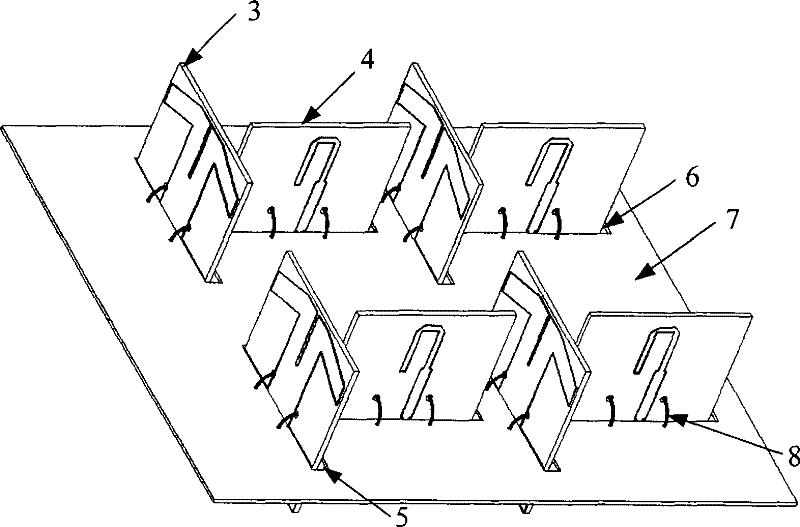
[0038] An L-band 3×8 unit dual-linearly polarized microstrip dipole antenna array, the structure diagram is as follows Figure 4 . The antenna array is composed of 24 radiating elements 1 , a conductor reflector 7 and three dual-polarization line feed networks 9 . Each radiating element is arranged in a rectangular grid order, in which there are 8 radiating elements in the row direction and 3 radiating elements in the column direction, and dx=0.62λ 0 ,dy=0.65λ 0 . Each radiating element is composed of a vertically polarized microstrip dipole antenna 3 and a horizontally polarized microstrip dipole antenna 4 arranged vertically in a "T" shape (the antenna unit used in the figure It is a well-known antenna unit in the art, and references can be seen: Brian Edward and Daniel Rees, A Broadband Printed Dipole with Integrated BALUN. MJ, 1987, 30 (5), PP339-344.). In order to facilitate the connection between each antenna unit and the line feed network, the conductor reflector 7 ...
Embodiment 3
[0043] A P-band 4×6 element dual-linearly polarized ultra-wideband antenna array, such as Figure 10 , the antenna unit is a microstrip Vivaldi antenna unit (reference: R. Janaswamy and D.H. Schaubert, Analysis of the tapered slot antenna, IEEE TAP., vol.35, pp.1058, Sept.1987.). In order to achieve the consistency of the phase centers of the two polarization states, each antenna unit adopts the following figure 2 The cell arrangement shown. Each antenna unit is directly fixed on the conductor reflection plate 7 by an L-shaped structural member 10 and fed by an N-shaped connector 11 . Take dx=0.5λ 0 ,dy=0.5λ 0 . The antenna array is simulated using the industry-recognized HFSS11.0 (high-frequency structure simulation software developed by Ansoft). Better than -25dB, port isolation better than 28dB.
PUM
 Abstract
Description
Claims
Application Information
 - R&D
- Intellectual Property
- Life Sciences
- Materials
- Tech Scout
- Unparalleled Data Quality
- Higher Quality Content
- 60% Fewer Hallucinations
Browse by: Latest US Patents, China's latest patents, Technical Efficacy Thesaurus, Application Domain, Technology Topic, Popular Technical Reports.
© 2025 PatSnap. All rights reserved.Legal|Privacy policy|Modern Slavery Act Transparency Statement|Sitemap|About US| Contact US: help@patsnap.com


