Bit allocation method and apparatus for multicarrier modulation signal, and system

a multi-carrier modulation and allocation method technology, applied in the field of communication, can solve the problems of introducing signal distortion, affecting the performance and high peak to average power ratio (papr), so as to reduce the burst errors of multi-carrier modulation signals

Active Publication Date: 2016-08-04
FUJITSU LTD
View PDF2 Cites 3 Cited by
  • Summary
  • Abstract
  • Description
  • Claims
  • Application Information

AI Technical Summary

Benefits of technology

[0008]In order to solve these problems pointed out in the Background, embodiments of the present disclosure provide a bit allocation method and apparatus for a multicarrier modulation signal and a system, so as to reduce burst errors of the multicarrier modulation signal.
[0016]An advantage of the embodiments of this application exists in that by presetting a signal to noise ratio margin for a clipping noise, tolerance of the signal for the clipping noise is increased, burst errors are reduced, and success of forward error correction (FEC) decoding is ensured.

Problems solved by technology

A problem exists in a multicarrier modulation signal is that its peak to average power ratio (PAPR) is relatively high.
In practical applications, a peak value of an output signal of a transmitter is usually limited.
The clipping method introduces signal distortion while lowering the PAPR and increasing the average power of the signal.
And on the other hand, as a multicarrier modulation signal is formed by superimposing multiple subcarrier signals, in some special bit patterns, an extremely high PAPR will occur, and performing clipping on symbols of the extremely high PAPRs will produce large signal distortion, resulting in occurrence of a burst error in the symbols.
Although a probability of occurrence of such a burst error is not high, which has quite small effect on the average bit error rate, such a burst error will cause invalidation of decoding of forward error correction (FEC), thereby resulting in communication failure.

Method used


Image

  • Bit allocation method and apparatus for multicarrier modulation signal, and system
  • Bit allocation method and apparatus for multicarrier modulation signal, and system
  • Bit allocation method and apparatus for multicarrier modulation signal, and system

Examples


embodiment 1

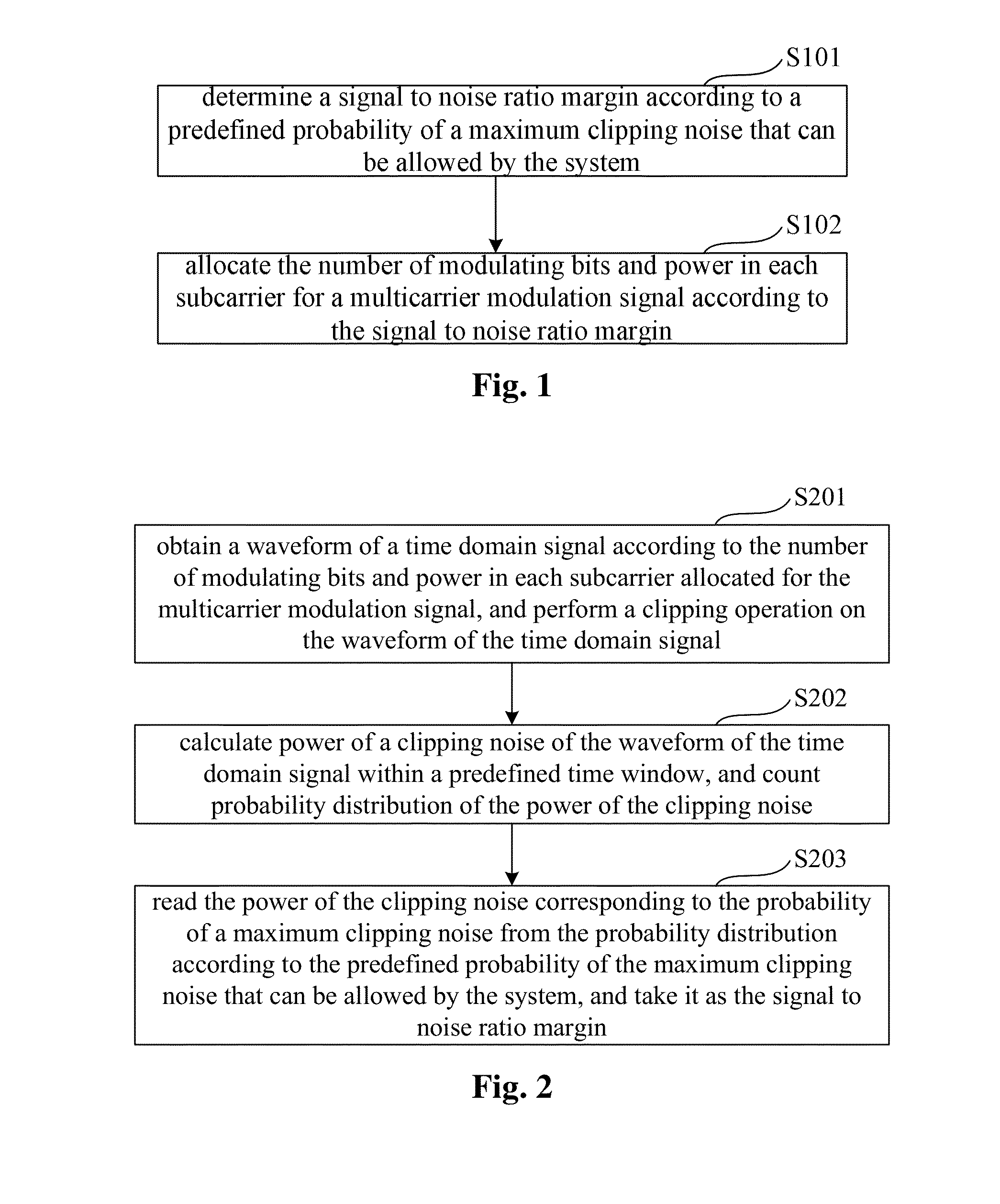
[0035]An embodiment of this application provides a bit allocation method of a multicarrier modulation signal. FIG. 1 is a flowchart of the method. Referring to FIG. 1, the method includes:

[0036]step 101: determining a signal to noise ratio margin according to a predefined probability of a maximum clipping noise that can be allowed by the system; and

[0037]step 102: allocating the number of modulating bits and power in each subcarrier for a multicarrier modulation signal according to the signal to noise ratio margin.

[0038]In step 101, the predefined probability of a maximum clipping noise that can be allowed by the system refers to a probability of occurrence to which a maximum clipping noise (clipping distortion) that can be allowed by the system to occur corresponds. A value of such a probability may be predefined; however, this embodiment is not limited thereto.

[0039]In an implementation, step 101 may be carried by using the method shown in FIG. 2. As shown in FIG. 2, the method in...

embodiment 2

[0057]An embodiment of the present disclosure further provides a bit allocation apparatus of a multicarrier modulation signal. As principles of the apparatus for solving problems is similar to that of the method according to Embodiment 1, the implementation of the method according to Embodiment 1 may be referred to for implementation of the apparatus, with identical contents being not going to be described herein any further.

[0058]FIG. 6 is a schematic diagram of a structure of the bit allocation apparatus of a multicarrier modulation signal according to this embodiment. Referring to FIG. 6, the apparatus 600 includes: a determining unit 601 and an allocating unit 602. In this embodiment, the determining unit 601 is configured to determine a signal to noise ratio margin according to a predefined probability of a maximum clipping noise that can be allowed by the system, and the allocating unit 602 is configured to allocate the number of modulating bits and power in each subcarrier fo...

embodiment 3

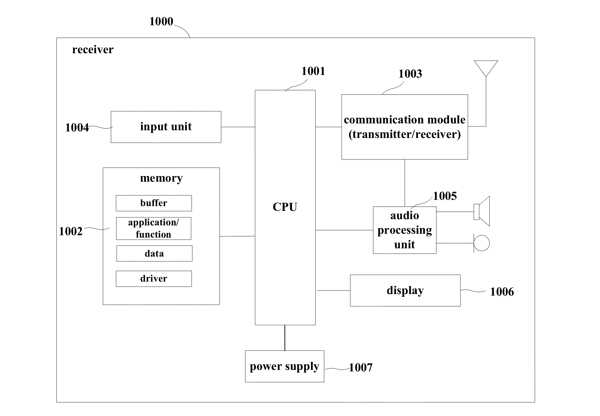
[0066]An embodiment of the present disclosure further provides a transmitter, such as a base station in a multicarrier communication system, the transmitter including the bit allocation apparatus of a multicarrier modulation signal according to Embodiment 2.

[0067]FIG. 9 is a schematic diagram of a structure of the transmitter of this embodiment. As shown in FIG. 9, the transmitter 900 may include a central processing unit (CPU) 901 and a memory 902, the memory 902 being coupled to the central processing unit 901. The memory 902 may store various data, and furthermore, store programs for information processing, and execute the programs under control of the central processing unit 901.

[0068]In an implementation, the functions of the bit allocation apparatus according to Embodiment 2 may be integrated into the central processing unit 901. In this implementation, the central processing unit 901 may be configured to determine a signal to noise ratio margin according to a predefined proba...


PUM


Abstract

A bit allocation method and apparatus for a multicarrier modulation signal and a system where the method includes: determining a signal to noise ratio margin according to a predefined probability of a maximum clipping noise that can be allowed by the system; and allocating the number of modulating bits and power in each subcarrier for a multicarrier modulation signal according to the signal to noise ratio margin. By presetting a signal to noise ratio margin for a clipping noise, tolerance of the signal for the clipping noise is increased, and bit error rate is efficiently lowered.

Description

CROSS-REFERENCE TO RELATED APPLICATIONS[0001]This application claims the benefit of Chinese Application No. 201510050257.2, filed Jan. 30, 2015, the disclosures of all of which are incorporated herein by reference.BACKGROUND OF THE INVENTION[0002]1. Field[0003]The present disclosure relates to the field of communications, and in particular to a bit allocation method and apparatus for a multicarrier modulation signal, and a system.[0004]2. Description of the Related Art[0005]Multicarrier modulation employs multiple subcarrier signals. It decomposes a data stream into several sub-data streams, so that the sub-data stream has a much lower transmission rate, and these data are respectively used to modulate several subcarriers. A multicarrier modulation signal features in that transmission rate of the subcarrier data is relatively low and the periods of code elements are relatively long, etc. The multicarrier modulation may be achieved by multiple technical means, such as discrete multi-...

Claims


Application Information

Patent Timeline
Patent Type & Authority Applications(United States)
IPC IPC(8): H04J11/00H04L27/26
CPCH04J11/0026H04L27/2623H04L27/2614H04L5/0046H04W52/241H04W52/346
Inventor CHEN, HAOLI, LEI
Owner FUJITSU LTD
Why Eureka
Try Eureka