Liquid discharge apparatus and control method of liquid discharge apparatus

Inactive Publication Date: 2016-08-11
SEIKO EPSON CORP
View PDF7 Cites 1 Cited by
  • Summary
  • Abstract
  • Description
  • Claims
  • Application Information

AI Technical Summary

Benefits of technology

The invention provides a liquid discharge apparatus and a control method that can quickly change the positions of a supporting unit and a maintenance unit without interfering with each other. This allows for more efficient use of the apparatus and reduces downtime for maintenance.

Problems solved by technology

However, each moving route of the platen unit and the cap unit is close to the line head side, and thus existence of an interference area, in which both units interfere with each other when both units pass though the moving route, is inevitable.
However, in a case where the platen unit and the cap unit are independently driven by two power sources, if the platen unit and the cap unit are driven at the same time, the platen unit and the cap unit are likely to interfere with each other.
On the other hand, in a case where one of the platen unit and the cap unit is moved first and then the other one starts to be moved, it is possible to avoid a case where both units interfere with each other; however, it takes relatively a long time to replace the positions both units with each other at the time of the maintenance.
In addition, this kind of problem commonly occurs in a serial printer and in even a liquid discharge apparatus for discharging a liquid other than ink without limiting to the line printer.
For this reason, the supporting unit and the maintenance unit are independently controlled, but both units may interfere with each other in the vicinity of a predetermined position.

Method used


Image

  • Liquid discharge apparatus and control method of liquid discharge apparatus
  • Liquid discharge apparatus and control method of liquid discharge apparatus
  • Liquid discharge apparatus and control method of liquid discharge apparatus

Examples


Embodiment Construction

[0066]Hereinafter, as an embodiment of a liquid discharge apparatus, an ink jet type printer which is provided with a discharging head for discharging ink an example of the liquid, and prints (records) an image including characters and figures by discharging the ink onto a sheet which is an example of a medium will be described with reference to the drawings.

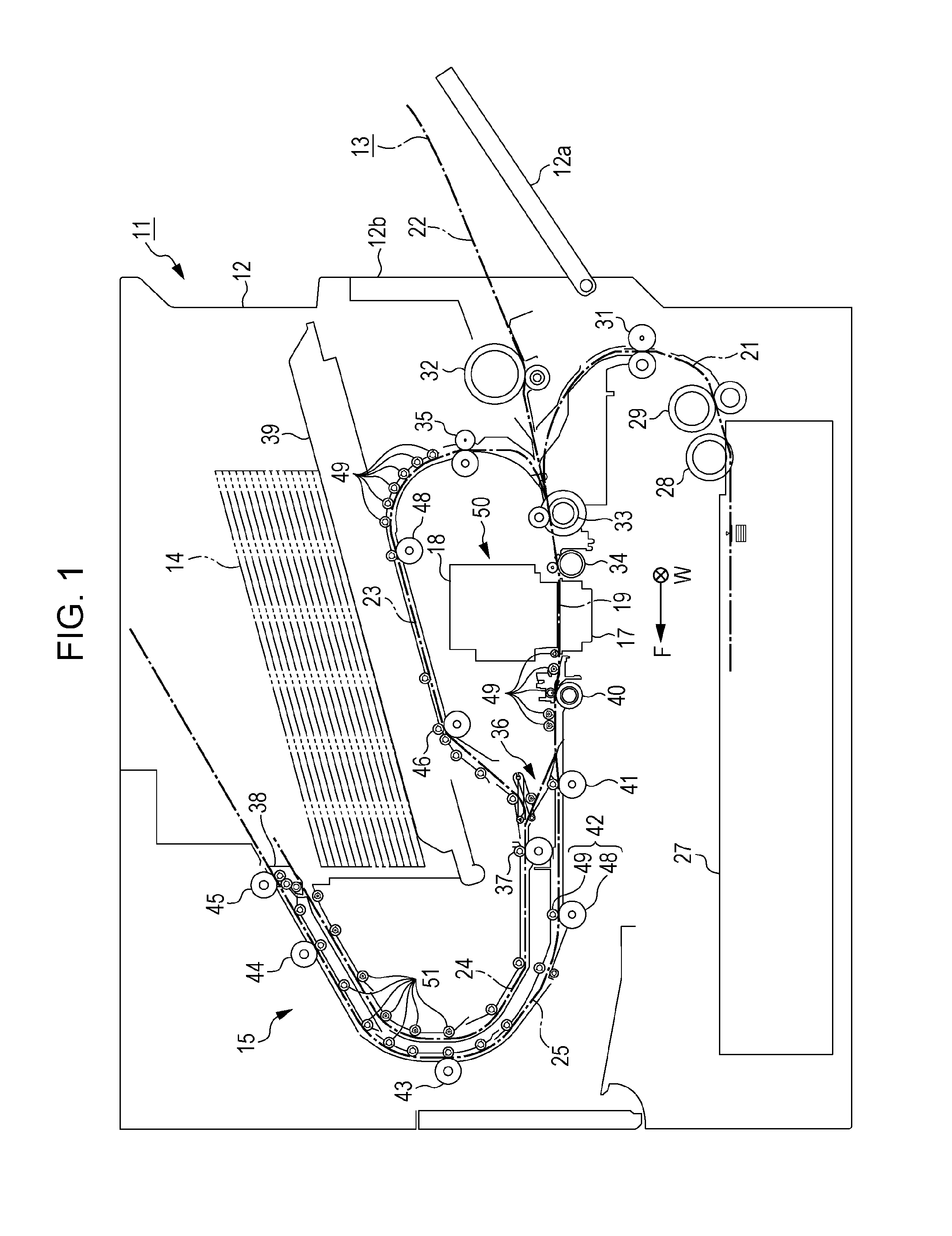
[0067]As illustrated in FIG. 1, as an example of a printing apparatus of the embodiment, a printer 11 is provided with a housing 12, and a transporting unit 15 which transports a sheet 14 and the housing 12 having a rectangular parallelepiped shape along a transporting route 13 illustrated by a dashed line in FIG. 1. Further, along the transporting route 13, a supporting base 17 as an example of a supporting unit for supporting the sheet 14 and a discharging head 18 which faces the supporting base 17 by interposing the transporting route 13 therebetween are fixedly disposed. In addition, in FIG. 1, a direction in which an area w...


PUM


Abstract

A printer is provided with a discharging head that discharges ink, a supporting base that supports a medium, and a cap that receives an ink droplet discharged from the discharging head at the time of maintenance (flushing) implementation. The supporting base and the cap are moved between an ascending position (a supporting position and a flushing position) facing the discharging head along different moving routes and a retractable position. When positions of the supporting base and the cap are replaced with each other so as to perform the flushing during the printing, if the supporting base is firstly retracted from the supporting position, and then a first sensor which detects the supporting base is turned on, the cap ascends from the retractable position. After the flushing, if the cap firstly descends, and then a second sensor which detects the cap is turned on, the supporting base starts to ascend.

Description

BACKGROUND[0001]1. Technical Field[0002]The present invention relates to a liquid discharge apparatus and a control method of the liquid discharge apparatus which is provided with a supporting base supporting a medium and a maintenance unit such as a cap which is used for maintenance of a discharging head for discharging a liquid with respect to the medium.[0003]2. Related Art[0004]In the related art, as such type of liquid discharge apparatus, an ink jet type printing apparatus which is provided with a discharging head (a printing head) for discharging ink as a liquid has been known. The ink jet type printing apparatus is provided with a supporting base (an example of a supporting unit) which supports a medium such as a sheet to be transported and a discharging head which discharges ink from a nozzle to the medium supported by the supporting base. In addition, in order to prevent nozzle clogging in the discharging head, a maintenance device which performs maintenance of the dischar...

Claims


Application Information

Patent Timeline
IPC IPC(8): B41J2/165
CPCB41J2002/16582B41J2/16517B41J2/16508B41J2/16511
Inventor KAKEGAWA, TOMOYOSHITOKUNAGA, MASAYUKIMUROMACHI, AKINORI
Owner SEIKO EPSON CORP
Why Eureka
Try Eureka