Cowl top cover

a top cover and cowl technology, applied in the direction of superstructure subunits, vehicle components, pedestrian/occupant safety arrangements, etc., can solve the problems of increased production costs and weakened sides of the cover section, and achieve the effect of improving the appearance promoting bending deformation of the cover section, and reducing production costs

Active Publication Date: 2016-08-11
NIHON PLAST CO LTD +1
View PDF0 Cites 4 Cited by
  • Summary
  • Abstract
  • Description
  • Claims
  • Application Information

AI Technical Summary

Benefits of technology

[0027]Furthermore, the swelling section includes an upper inclined section and a lower inclined section inclined toward one side in a vehicle length direction from the cover section body, and a gradually decreasing section disposed on both left and right sides of the upper inclined section and the lower inclined section, causing a swelling amount with respect to the cover section body to gradually decrease toward the left and right side edge sides of the cover section. The swelling section of the cover section is thus configured, whereby the swelling section can be efficiently provided in a central region in the vehicle width direction in the cover section, and the quality of appearance of the cover section (appearance) can be improved.
[0028]In this case, a ridge section between the upper inclined section and the lower inclined section in the swelling section is disposed lower than a height position of a center line in a vehicle height direction of the cover section along a vehicle width direction. As a result, when the vertical wall section receives the stress (load) in the direction of being crushed, the stress can be effectively focused on the swelling section of the cover section, and the bending deformation of the cover section can be stably promoted.
[0029]In addition, the recessed groove section is recessed on the surface facing the other side in the vehicle length direction in the cover section body and the swelling section, and the recessed groove section is disposed corresponding to the height position where the ridge section between the upper inclined section and the lower inclined section in the swelling section is disposed. The recessed groove section is thus provided, whereby the recessed groove section can also function as the bending promotion section of the cover section, and therefore the entire cover section can be more stably deformed in a manner so as to be crushed in the vehicle height direction.
[0030]Furthermore, in an upper end section and a lower end section of the cover section, an upper side claw section and a lower side claw section engageable with and disengageable from the vertical wall body are respectively disposed, and the upper side claw section and the lower side claw section are disposed in a position in the vehicle width direction corresponding to a forming region in the vehicle width direction of the swelling section. As a result, the stress (impact force) the cowl top cover receives can be caused to efficiently act on the cover-side bending promotion section of the cover section, and therefore the cover section can be quickly and reliably bent and deformed on one direction side by the cover-side bending promotion section.
[0031]Moreover, the upper side claw section and the lower side claw section of the cover section are disposed in the position corresponding to the end section of the swelling section in the vehicle width direction, in other words, the swelling section is disposed between the sections where the left and right upper side claw sections and the lower side claw sections are locked to the vertical wall body in the vehicle width direction, whereby when the vertical wall body is deformed in a manner so as to be crushed, the cover section receiving the stress is also easily crushed so that the swelling section given a shape in advance is caused to protrude in the swelling direction, and the cover section is partially lifted from the opening of the vertical wall body to be easily removed. Thereby, the impact of the cover section on the deformation of the vertical wall body can be extremely reduced, and the cowl top cover can be quickly and stably crushed, and therefore the impact absorption function can be effectively exhibited.
[0032]Furthermore, at least one reinforcement vertical rib is disposed in the cover section of the cowl top cover of the invention, and the reinforcement vertical rib has a bent form so as to protrude in the direction where the cover-side bending promotion section prompts the bending deformation (for example, frontward). The reinforcement vertical rib has this form, whereby the cover section can be reinforced, and when the cover section is bent and deformed prompted by the cover-side bending promotion section, the reinforcement vertical rib also can be stably bent and deformed, and therefore the cover section can be stably crushed.

Problems solved by technology

However, when an object collides, for example, from a direction along the position of the elevation surface of the cover section, the effect of sliding the upper side of the opening with respect to the inclined side of the cover section is weakened, and the direction of the elevation surface of the cover section matches the downward direction of the collision object, and therefore there is a concern that the cover section supports the vertical wall section.
Therefore, the production cost is increased, and the design limitations such as the rib and the like being made relatively larger, the cover section being made relatively smaller, or the opening being arranged in the lower part of the vertical wall section occur, and therefore there is a problem that it is difficult to configure the cover section and the opening so that the usability is improved.

Method used


Image

  • Cowl top cover
  • Cowl top cover
  • Cowl top cover

Examples


second embodiment

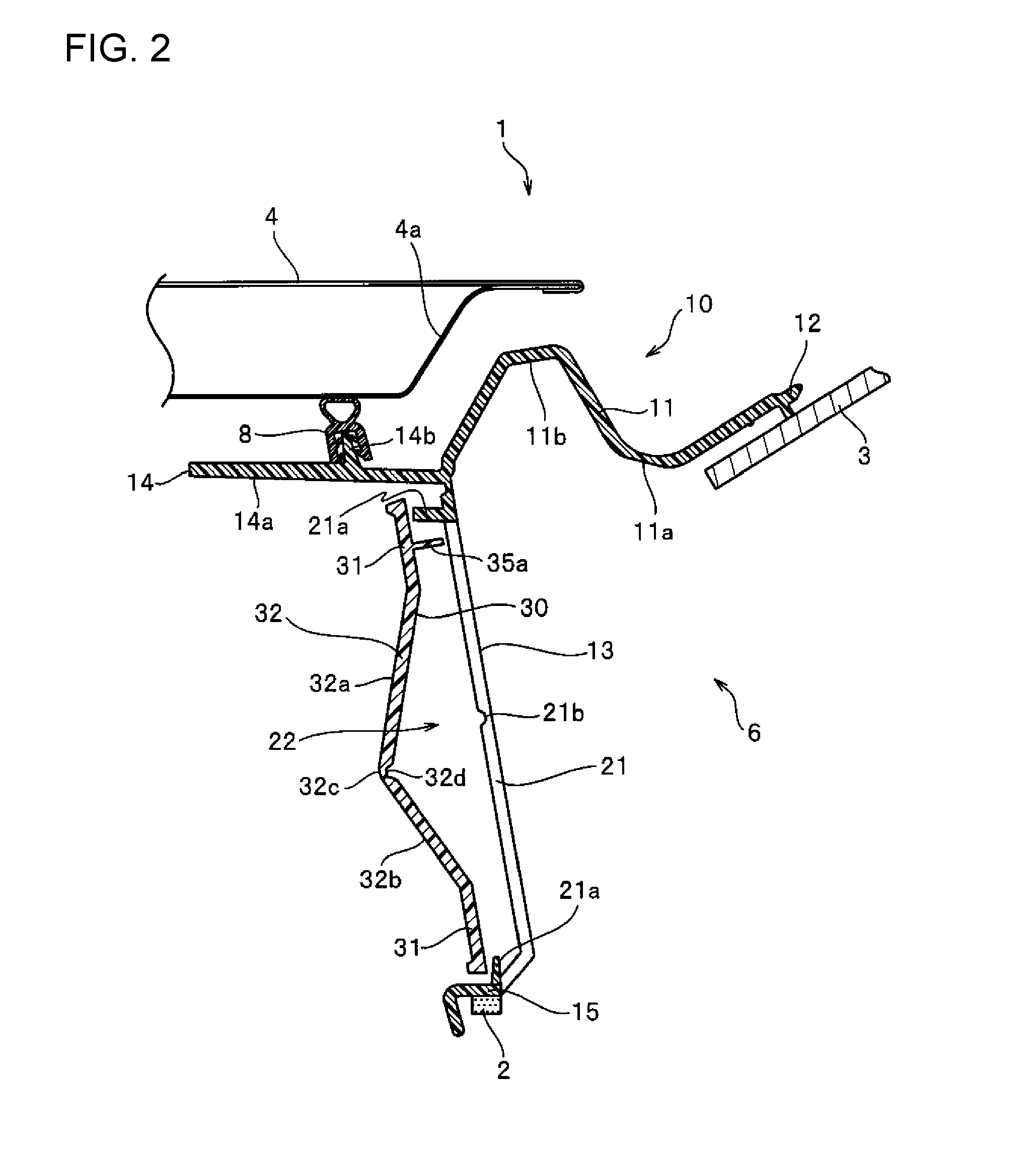
[0093]FIG. 9 is a cross-sectional view showing a cross-section of the cowl top cover according to the second embodiment of the invention. FIGS. 10 and 11 are perspective views of a cover section of the cowl top cover seen obliquely from the front and rear sides. It should be noted that in the present second embodiment and the third embodiment described below, although the form of the cover section of the cowl top cover is different, the configuration other than the cover section is substantially the same as those in the cowl top cover in the above-described first embodiment, and therefore the description will be made by focusing on the cover section, and the same member as in the first embodiment described above will be represented by using the same reference numerals, whereby the detailed description will be omitted.

[0094]The vertical wall section 13 of the cowl top cover 10b in the present second embodiment includes a vertical wall body 21, an opening 22 formed in the vertical wal...

third embodiment

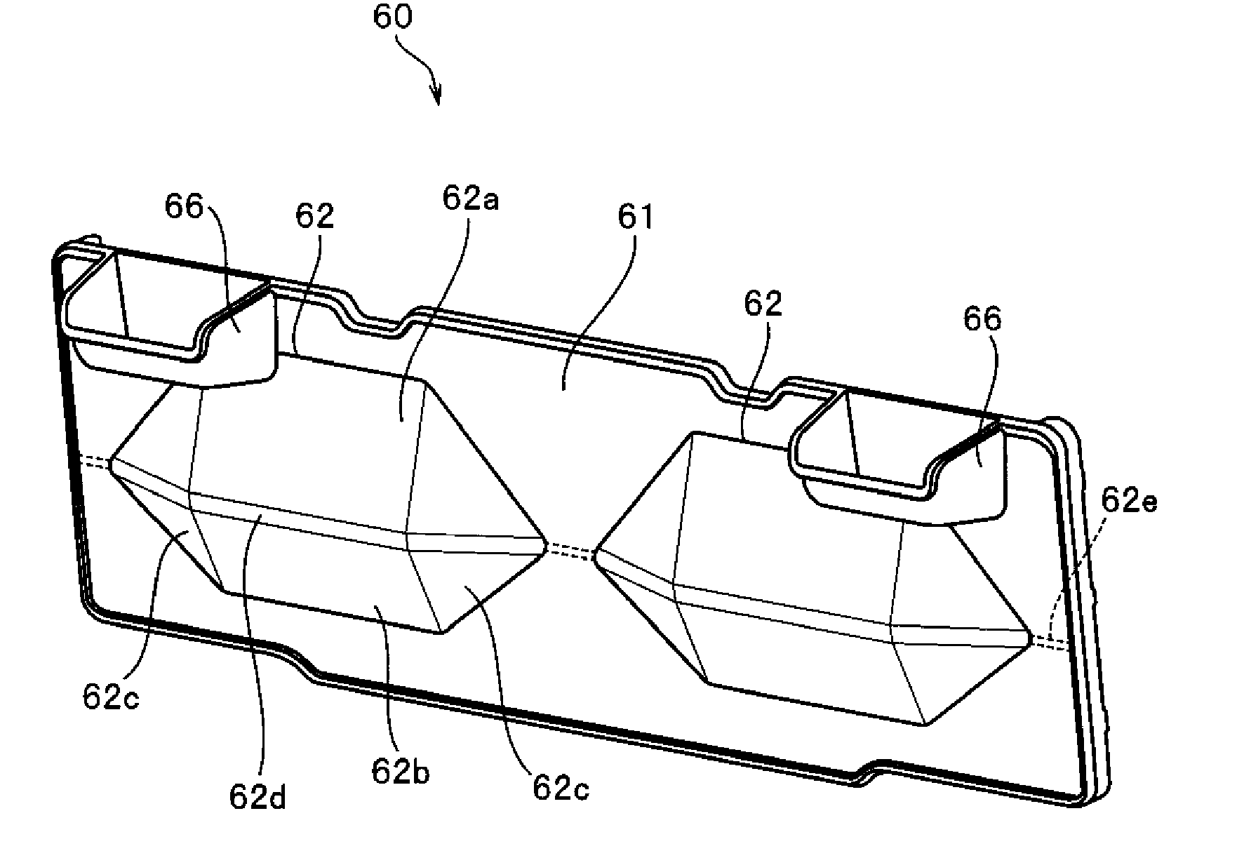
[0106]FIG. 12 is a perspective view of a cover section of the cowl top cover seen obliquely from the front side according to the present third embodiment.

[0107]The cover section 60 in the present third embodiment includes a cover section body 61, and two swelling sections 62 configured to swell in a V-shape on the front side with respect to the cover section body 61 when the cross section perpendicular to the vehicle width direction is viewed. In particular, the two swelling sections 62 in the present third embodiment are bilaterally symmetrically formed with respect to the center line in the vehicle width direction of the cover section 60, and a flat cover section body 61 is disposed in the region on the left and right side edge sides of the cover section 60 and in the region between the two swelling sections 62.

[0108]In this case, the left and right two swelling sections 62 are disposed so that the sum of the maximum dimension in the vehicle width direction of each of the swelling...


PUM


Abstract

This cowl top cover has a cover body section and a vertical wall section which extends vertically from the front end of the cover body section. The vertical wall section is provided with a vertical wall body, an opening which is formed in the vertical wall body, and a cover section has a cover-side bending promotion section which extends in the width direction of the vehicle and which promotes the bending and deformation of the cover section to one side of the length direction of the vehicle. As a result of this configuration, the cowl top cover can consistently exhibit a sufficient impact absorption function when subjected to an impact.

Description

CROSS-REFERENCE TO RELATED APPLICATIONS[0001]This application is the U.S. National Phase of International Patent Application Serial No. PCT / JP2014 / 075582, filed Sep. 26, 2014, which claims priority to Japanese Patent Application No. 2013-213083, filed Oct. 10, 2013, both of which are herein incorporated by reference in their entireties.TECHNICAL FIELD[0002]The invention relates to a cowl top cover configured to cover a cowl section disposed between a windshield and a hood of a vehicle.BACKGROUND[0003]For example, in Japanese Unexamined Patent Application Publication No. 2011-5988 A (JP '988), in the structure where an opening is disposed in the vertical wall section of the cowl top cover, and a cover section for closing the opening is attached to the vertical wall section, the technique where a rib is disposed on the inner surface facing inside the cowl section of the cover section for closing the opening, and an inclined side is formed on the rib is disclosed.[0004]According to the...

Claims


Application Information

Patent Timeline
Patent Type & Authority Applications(United States)
IPC IPC(8): B62D25/08B62D25/12
CPCB62D25/081B62D25/12B60R2021/343B60R21/34B60R13/04B62D25/08
Inventor ISHIHARA, RYOSANO, CHIKARAIWATA, NAOKAMEOKA, HIDENORI
Owner NIHON PLAST CO LTD
Why Eureka
Try Eureka